I tried to find this. But I can't see it in:Up to 500W peak for a short time period for e.g. 200ms.
http://www.vitrohm.com/content/files/vitrohm_series_kh_-_201501.pdf
I did find "Energy Capability graph" for 208-8, but I don't know what is is telling me.
How?The circuit is tolerant for using NTCs instead too.
NTCs in series work. NTCs in parallel risk current hogging.
Where have I said paralleled NTC's?How?
NTCs in series work. NTCs in parallel risk current hogging.
.............. I have taken the decision to go for parallel VITROHM..................Using 4 smaller resistors paralleled is tolerant for up to 2 defective resistors.
The circuit is tolerant for using NTCs instead too...............
that reads that you are saying the NTCs in parallel can be used in lieu of the resistors in parallel.Where have I said paralleled NTC's?
http://www.vitrohm.com/content/files/pulse_load_wirewound_resistors_-_201508.pdfI tried to find this. But I can't see it in:
http://www.vitrohm.com/content/files/vitrohm_series_kh_-_201501.pdf
I did find "Energy Capability graph" for 208-8, but I don't know what is is telling me.
Really?that reads that you are saying the NTCs in parallel can be used in lieu of the resistors in parallel.
astx, I see you changed the Noctuas for somethin else, Papst maybe. Was something wrong with them?
Dear Leucetius,astx, I see you changed the Noctuas for somethin else, Papst maybe. Was something wrong with them?
nothing wrong - these are very good fans - speed can only be controlled by DC voltage. But my MIC502/NTC based fan controller is a classic PWM controller hence I need to find equivalent low noise PWM controllable fans and found San Ace 60 (model 9S0612F401 / Sanyo Denki) to be the (low noise) winner. I drive the MIC502 at > 25kHz pwm (using 100pF instead of 150nF caps; using Toshibas fast CMOS driver IC TBD62083A) to reduce the fan introduced mechanical noise and to keep the electronic noise above hearable frequencies.
A real DC based fan controller using the new DAC output capable PIC microcontrollers is on my todo list to support the ultra silent Noctuas ...
BR, Toni
housekeeping circuits - final hardware version 4.3
... gerbers ...
NOTE: Schematics and/or pcb gerber files are free to use only for non commercial DIY projects!
BR, Toni
... gerbers ...
NOTE: Schematics and/or pcb gerber files are free to use only for non commercial DIY projects!
BR, Toni
Attachments
SA2015: using lateral mosfets EXC10N20 EXC10P20
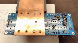
... preparations for SA2015 lateral MOSFET amplifier beta test ...
The new PCB has been designed for lateral MOSFETs from Exicon:
... preparations for SA2015 lateral MOSFET amplifier beta test ...
The new PCB has been designed for lateral MOSFETs from Exicon:
- ECX10N20
- ECX10P20
Attachments
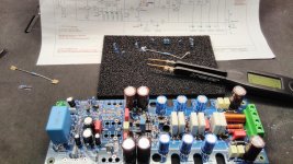
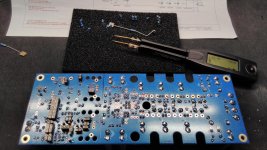
Sockets ideal for quick part change, realy beta version!... preparations for SA2015 lateral MOSFET amplifier beta test ...
The new PCB has been designed for lateral MOSFETs from Exicon:
- ECX10N20
- ECX10P20
I wish you good luck!
Very professional job as usual.🙂
SA2013, SA2014, SA2015 - output coil - making of
Thx!
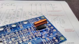
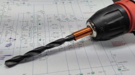
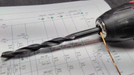
My quick 'n dirty method to create the coils used in my power amplifier projects:
Thx!
My quick 'n dirty method to create the coils used in my power amplifier projects:
- get 55cm of 1mm diameter enamelled copper wire
- bend 1cm as shown in picture 1
- use 7mm diameter drill
- insert wire
- rotate slow counter clockwise using battery screwdriver
- 18 - 19 full turns ...
- depending on the final diameter your coils inductivity is between 0.8 to 1.1 µH
Attachments


Very nice method! The ones I wound by hand were awful compared with yours. Needless to say, yours have been soldered into my boards and mine went to trash.
Hi Astx, congrats on your new MOSFET design. Have you done any tests to see how consistent Vgs is between the Exicon parts?
It would be useful for the Exicon models to have that information as well as some Vgs vs ID data to confirm modeling in the subthreshold region.
It would be useful for the Exicon models to have that information as well as some Vgs vs ID data to confirm modeling in the subthreshold region.
Thx!Hi Astx, congrats on your new MOSFET design. Have you done any tests to see how consistent Vgs is between the Exicon parts?
It would be useful for the Exicon models to have that information as well as some Vgs vs ID data to confirm modeling in the subthreshold region.
The next days I can do some DCA75pro scans but the data may be not meaningful due to the low ID capability of the DCA75pro of max. 12 - 15mA.
Some data from my transistor matcher to see how much a lot of 30 pieces are different...
Code:
ECX10N20:
#       Vgs_low V       Vgs_high V
25      0.200   0.561
20      0.200   0.561
30      0.200   0.563   X
24      0.201   0.563   X
23      0.201   0.563   X
17      0.199   0.564
27      0.201   0.564
28      0.201   0.564
22      0.203   0.564
18      0.199   0.565
21      0.203   0.565
19      0.200   0.566
5       0.206   0.569
11      0.207   0.569
4       0.207   0.569
12      0.208   0.570
14      0.208   0.570
10      0.206   0.571
8       0.208   0.571
13      0.207   0.572
7       0.209   0.572
1       0.208   0.573
2       0.210   0.573
15      0.208   0.574
3       0.209   0.574
6       0.211   0.574
9       0.209   0.578
29      0.202   0.587
26      0.201   0.590
16      0.210   0.600
Code:
ECX10P20:
#       Vgs_low V       Vgs_high V
6       -0.665  -1.104
1       -0.675  -1.099
4       -0.678  -1.093
5       -0.667  -1.086
26      -0.639  -1.084
20      -0.659  -1.083
21      -0.658  -1.079
9       -0.653  -1.077
11      -0.651  -1.077
10      -0.651  -1.077
2       -0.657  -1.076
3       -0.654  -1.075
7       -0.648  -1.075
12      -0.645  -1.073
14      -0.646  -1.070
8       -0.643  -1.070
17      -0.646  -1.069
27      -0.645  -1.068
19      -0.644  -1.068
15      -0.642  -1.068
29      -0.643  -1.067
16      -0.635  -1.067
28      -0.647  -1.065
24      -0.640  -1.064
18      -0.637  -1.064
22      -0.637  -1.063  X
30      -0.645  -1.062  X
23      -0.636  -1.062  X
25      -0.634  -1.060
13 -0.631 -1.054- Vgs low: supply 10V and 2k in series with Drain/Source
- Vgs high: supply 10V and 100R in series with Drain/Source
BR, Toni
Lateral mosfets - measurement data
Voila...
ECW20N20Z
ECW20P20Z
ECW20N20
ECW20P20
ECX10N20
ECX10P20
BR, Toni
Voila...
Code:
ECW20N20Z
N-Ch Enhancement mode MOSFET
Red-D Green-S Blue-G
Vgs(on)=0,173V at Id=5,03mA and Ig=0µA
Vgs(off)=-0,109V at Id=5,5µA
gm=69,5mA/V at Id=3,1mA to 5,0mA
Rds(on)<1.0O at Id=5,0mA and Vgs=8,0V
with body diode

ECW20P20Z
P-Ch Enhancement mode MOSFET
Red-D Green-S Blue-G
Vgs(on)=0,596V at Id=4,98mA and Ig=2µA
Vgs(off)=0,262V at Id=4,8µA
gm=53,3mA/V at Id=3,0mA to 5,0mA
Rds(on)<1.0O at Id=5,0mA and Vgs=8,0V
with body diode

ECW20N20
N-Ch Depletion mode MOSFET
Red-D Green-S Blue-G
Vgs(on)=0,146V at Id=5,04mA and Ig=0µA
Vgs(off)=-0,136V at Id=5,1µA
gm=81,1mA/V at Id=3,0mA to 5,0mA
Rds(on)<1.0O at Id=5,0mA and Vgs=8,0V
with body diode

ECW20P20
P-Ch Enhancement mode MOSFET
Red-D Green-S Blue-G
Vgs(on)=0,567V at Id=4,97mA and Ig=0µA
Vgs(off)=0,219V at Id=4,7µA
gm=70,0mA/V at Id=3,0mA to 5,0mA
Rds(on)=1,3O at Id=5,0mA and Vgs=8,0V
with body diode

ECX10N20
N-Ch Enhancement mode MOSFET
Red-D Green-S Blue-G
Vgs(on)=0,186V at Id=5,02mA and Ig=2µA
Vgs(off)=-0,110V at Id=5,4µA
gm=69,5mA/V at Id=3,0mA to 5,0mA
Rds(on)<1.0O at Id=5,0mA and Vgs=8,0V
with body diode

ECX10P20
P-Ch Enhancement mode MOSFET
Red-D Green-S Blue-G
Vgs(on)=0,614V at Id=4,96mA and Ig=3µA
Vgs(off)=0,252V at Id=5,4µA
gm=51,9mA/V at Id=3,0mA to 5,0mA
Rds(on)=1,1O at Id=5,0mA and Vgs=8,0V
with body diode
ECW20N20Z
ECW20P20Z
ECW20N20
ECW20P20
ECX10N20
ECX10P20
BR, Toni
Attachments
SA2016: using lateral mosfets EXC10N20 EXC10P20
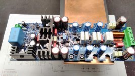
😱 Found 3 (!) mask errors on PCB (so all prototype pcb's are unusable without some mechanical rework). Each mask error has created a short circuit to ground.😱
After removing some copper the amplifier started to work without any problems. 🙂
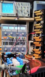
First tests with only one pair of EXC10N20/10P20 with 100mA bias running at +/- 30V DC are very promising:
Clipping: excellent behaviour as SA2014 and SA2015 V-MOSFET.
Wow!
More data will follow after populating all pairs...
BR, Toni
99 % ready for beta testing.
Need only BJT/MOSFET isolation and a final hardware check.
Have fun, Toni
😱 Found 3 (!) mask errors on PCB (so all prototype pcb's are unusable without some mechanical rework). Each mask error has created a short circuit to ground.😱
After removing some copper the amplifier started to work without any problems. 🙂
First tests with only one pair of EXC10N20/10P20 with 100mA bias running at +/- 30V DC are very promising:
- 1k@1W@8R THD+N < 0.0025 %
- 20k@1W@8R THD+N < 0.0035 %
- 1k@30W@8R THD+N < 0.00095 %
- 20k@30W@8R THD+N < 0.0045 %
Clipping: excellent behaviour as SA2014 and SA2015 V-MOSFET.
Wow!
More data will follow after populating all pairs...
BR, Toni
Attachments
Last edited:
SA2016: using lateral mosfets EXC10N20 EXC10P20
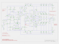
Schematics - preliminary!
NOTE: Schematics and/or pcb gerber files are free to use only for non commercial DIY projects!
BR, Toni
Schematics - preliminary!
NOTE: Schematics and/or pcb gerber files are free to use only for non commercial DIY projects!
BR, Toni
Attachments
- Home
- Amplifiers
- Solid State
- 2stageEF high performance class AB power amp / 200W8R / 400W4R