You are welcome! Thank you for your models!Thanks a lot for that data astx.
BR, Toni
Moderator: please move post 1703 - 1710
to this new thread:
http://www.diyaudio.com/forums/solid-state/294790-using-ltspice-check-soa-violations.html
All others: please post LTSpice/SOA related to this new thread.
Thx in advance! This post can be deleted afterwards.
BR, Toni
to this new thread:
http://www.diyaudio.com/forums/solid-state/294790-using-ltspice-check-soa-violations.html
All others: please post LTSpice/SOA related to this new thread.
Thx in advance! This post can be deleted afterwards.
BR, Toni
SA2016: using lateral mosfets EXC10N20 EXC10P20
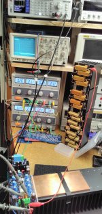
... very difficult to get the multi pair exicons stable. Perhaps my beta test layout (socketed gate resistors; long wires to gate) is the problem. Increasing the gate resistors from 220R to 330R helps a little bit but does not cure the oscillations.
1kHz small signal output 1W at 8R load resistor during tests:
The oscillations start (frequency around 21mHz) if I increase the bias higher as 100mA per pair. The THD+N increases from a good 0.002% up to 0.015% and the oscillation is viewable dancing on the 1kHz sinus.
Anybody with experience using those EXC10N20/EXC10P20 mosfets - just to be sure - could the 21MHz oscillation be from the Exicon's or do they tend to oscillate with higher frequencies?
Thanks in advance, Toni
SA2016: using lateral mosfets EXC10N20 EXC10P20
... got it. 🙂
6 x RC combination (100pF + 47R) from gate to drain as short as possible - subtle 21 MHz oscillations are gone. 🙂
Some THD+N values @ +/- 42V regulated power supply, bias ~ 85mA per device, 8R resistive load:
1k@70W 0.00060%
20k@70W 0.0048%
1k@50W 0.00063%
20k@50W 0.0046%
1k@50W 0.00078%
20k@50W 0.0041%
1k@1W 0.0019%
20k@1W 0.0026%
SNR referenced to 70W@8R
103.5 dB wideband, 111dB bw 80k, 117dB bw 20k, 120.5dB A-weighted
SNR referenced to 1W@8R
85 dB wideband, 94dB bw 80k, 99dB bw 20k, 102dB A-weighted
Slewrate > 100V/µS symmetric
BR, Toni
Do the RCs allow you to reduce the gate stoppers?
I've seen 20MHz and 100MHz oscillation on the bench, but I'm not sure it was even coming from the Exicons. All I had to do was touch the heatsink or volume knob and it would change.
I've seen 20MHz and 100MHz oscillation on the bench, but I'm not sure it was even coming from the Exicons. All I had to do was touch the heatsink or volume knob and it would change.
Last edited:
Gate resistor look symmetric. So, how about Ciss between N & P channel?! I wonder about that when Exicon sells their new generation MOSFET, ECX10N20/ECX10P20 - Not suffix ''R'' like old version.
I usually use Rg = 220R for P channel, 330R for N channel and attached with 100pF caps from Gate to Drain.
BTW, Nice slew rate.
Regard,
I usually use Rg = 220R for P channel, 330R for N channel and attached with 100pF caps from Gate to Drain.
BTW, Nice slew rate.
Regard,
Thx! That will be the next step: looking for lowest possible/stable gate resistor when RCs are attached.Do the RCs allow you to reduce the gate stoppers?
...
BR, Toni
Gate resistor look symmetric. So, how about Ciss between N & P channel?! I wonder about that when Exicon sells their new generation MOSFET, ECX10N20/ECX10P20 - Not suffix ''R'' like old version.
I usually use Rg = 220R for P channel, 330R for N channel and attached with 100pF caps from Gate to Drain.
BTW, Nice slew rate.
Regard,
Thx! Your Rg values are well known here from an application note for ALFETs where N-channel Ciss is 500pF and P-channel Ciss is 730pF.
But the newest datasheets from EXICON ecx10(n|p)20 show the same Ciss and transconductance for N- and P-channel.
I have posted a table with newest datasheets Ciss values here: EXICON Ciss/Rgate calculation table
True or a copy and paste error? Thats why I have choosen 220R for N- and P-channel gate resistors.
BR, Toni
Last edited:
...
1k@50W 0.00063%
20k@50W 0.0046%
1k@50W 0.00078%
20k@50W 0.0041%
...
corrected table:
1k@70W 0.00060%
20k@70W 0.0048%
1k@50W 0.00063%
20k@50W 0.0046%
1k@25W 0.00078%
20k@25W 0.0041%
1k@1W 0.0019%
20k@1W 0.0026%
(all measurements with analyzer bw 80kHz)
BR, Toni20k@70W 0.0048%
1k@50W 0.00063%
20k@50W 0.0046%
1k@25W 0.00078%
20k@25W 0.0041%
1k@1W 0.0019%
20k@1W 0.0026%
(all measurements with analyzer bw 80kHz)
Last edited:
...
But the newest datasheets from EXICON ecx10(n|p)20 show the same Ciss and transconductance for N- and P-channel.
I have posted a table with newest datasheets Ciss values here: EXICON Ciss/Rgate calculation table
True or a copy and paste error?
...
This must be a datasheet error. Still slightly unstable using RC 100pF+47R and Rgate all 220R. After changing N-channel to 330R stability for a bias from as low as 30mA per device to 300mA is mostly given.
Due to still some invisible instability (my spectrum analyzer range is 40MHz) I have added extra 27pF caps from gate to drain. Now no signs of instability viewable. High output power distortions worsens a little bit with this extra 27pF (THD20k@70W from 0.0035% to 0.0045%).
With this extra cap I have tried Rgate as low as 180R for N-channels and Rgate 120R for P-channels. Stable so far - no sign of instability if bias will be increased from 30mA to 300mA. THD as above.
Next step:
- removing 27pF caps and
- try to tune the RCs to get some bandwith and thus THD performance back...
BR, Toni
Yes - maybe one with good contacts to exicon can write an email to clarify the details?
Just have tried with 220pF/33R snubber.
Doesn't cure the high bias with suddenly increased THD problem. Rgate N channel increased from 180R to 330R and P channel from 120R to 220R with this snubber doesn't help either.
Tomorrow I remove the snubber and will try different G/D caps - starting with 100pF as you are using.
A stable configuration can be achieved using:
P.S.: The new datasheet contains this text: "Enhanced oscillation suppression in multi-device applications". 😱 What the hell was needed with earlier devices from exicon to get them stable?
Just have tried with 220pF/33R snubber.
Doesn't cure the high bias with suddenly increased THD problem. Rgate N channel increased from 180R to 330R and P channel from 120R to 220R with this snubber doesn't help either.
Tomorrow I remove the snubber and will try different G/D caps - starting with 100pF as you are using.
A stable configuration can be achieved using:
- Gate stopper N/P channel: 330R/220R
- G/D RC snubber 100pF + 47R
- G/D capacitor 27pF
P.S.: The new datasheet contains this text: "Enhanced oscillation suppression in multi-device applications". 😱 What the hell was needed with earlier devices from exicon to get them stable?
Great, Toni,
Let find best way to destroy oscillation, i will follow that result and become my reference for LMOS output stage.
Regard,
Let find best way to destroy oscillation, i will follow that result and become my reference for LMOS output stage.
Regard,
I can't help feeling the main problem is the distance of the O/P stage from the previous stage. IMHO, 50mm is too far but ju..uust doable with multiple O/P devices in a 200W 8R amp.
With a more compact layout, its always less necessary to use the 'snubbers'. Applies to all topologies I've played with.
With a more compact layout, its always less necessary to use the 'snubbers'. Applies to all topologies I've played with.
how should the three wires be dressed?I can't help feeling the main problem is the distance of the O/P stage from the previous stage. IMHO, 50mm is too far but ju..uust doable with multiple O/P devices in a 200W 8R amp.
With a more compact layout, its always less necessary to use the 'snubbers'. Applies to all topologies I've played with.
All tightly bundled, or all separated, or one separated and two twisted?
Which one is separate?
I can't help feeling the main problem is the distance of the O/P stage from the previous stage. IMHO, 50mm is too far but ju..uust doable with multiple O/P devices in a 200W 8R amp.
With a more compact layout, its always less necessary to use the 'snubbers'. Applies to all topologies I've played with.
The L-MOSFET amplifier itself is stable. No signs of instability viewable.
The V-MOSFET variant (IRFP240/IRFP9240) of this amplifier is rock stable with 150R gate stopper resistors. The pcb layout is nearly the same!
The subtle higher distortions start when the bias will be increased to above 100mA per device and hence the interaction between the OPS devices will increase too.
I think this is more a problem of the too less distance between the OPS devices. The gate stopper resistors are less as 5 mm in distance to the OPS devices plastic body - but how to get shorter?
This text from the datasheet
"Enhanced oscillation suppression in multi-device applications"
implies that problems using multiple pairs of EXICONs may arise.
Note: with only one pair of devices installed there wasn't any oscillation viewable. I've bought my lot of EXICONS in spring 2016 but the date code seems to be 2015 (S1522/S1535). Maybe they have send me devices which don't have this enhanced oscillation suppression?
BTW: haven't we found out during development of the high performance SA2014 amplifier that the distance from IPS/VAS to OPS doesn't play such a big role (speed of light) if correctly compensated. My 8 pairs SA2014 has a distance from OPS to VAS of minimum 250mm and maximum of 600mm due to the many devices!
BR, Toni
- Home
- Amplifiers
- Solid State
- 2stageEF high performance class AB power amp / 200W8R / 400W4R