Sounds great OS.
Take a look at my attachment, does it look somewhat correct? What value would you recommend for R19 at 80v?
I used this amp almost for a month earlier, and is now waiting for me to complete the cabinet for it. Ive fitted the honey badger with 4 pairs of outputs instead of 3. It seems to work pretty good, except i get some banging in my speaker when i reach high sound levels with much peaks of bass, and after i saw the posts these latest days, i though maybe that could be the cause for the bangs. Other than this, honey badger rocks with 4 outputs.
Are you running with Plus/Minus 80 rails? WOW

Here's the basic thing. Values aren't shown because it's not one-size-fits-all. I suggest using low-capacitance schottkeys. Some diodes actually have too low voltage drop and leakage is too large in this position, I think the 1N5817 is an example (but I think that has too much capacitance anyways).
Tried it , your right ... not any diode - you must use a VERY low reverse leakage
device or distortion increases a hundred-fold (NO
1N4148/914).Cod3gen's model , my MUR models, or my NPX diode model show almost no increase in distortion.
When you overdrive ,it is not asymmetrical , and it will clip before saturation.
It could be useful for "throttling" a sub amp (as dan says). Wherever you put
a diode in this amp's signal path , it better be a good (exceptional) one.
OS
Attachments
Here's the basic thing. Values aren't shown because it's not one-size-fits-all. I suggest using low-capacitance schottkeys. Some diodes actually have too low voltage drop and leakage is too large in this position, I think the 1N5817 is an example (but I think that has too much capacitance anyways).
Tried it , your right ... not any diode - you must use a VERY low reverse leakage
device or distortion increases a hundred-fold (NO
1N4148/914).Codegen's model , my MUR models, or my NPX diode model show almost no increase in distortion.
When you overdrive ,it is not asymmetrical , and it will clip before saturation.
It could be useful for "throttling" a sub amp (as dan says). Wherever you put
a diode in this amp's signal path , it better be a good (exceptional) one.
OS
Ah, well, the clippers should be quite delightful for a bass amp. Can you check a Series pair of bat86 set antiparallel with series pair bat86? That should be fairly quiet until about 0.587v or so, whereupon it will sound like a bright texture upon the bass or some fuzz, but this is a bit quieter than regular clipping, and a lot quieter than x-max.
P.S.
For full bandwidth amp, a jfet is probably more desirable than diode switching noises.
P.S.
For full bandwidth amp, a jfet is probably more desirable than diode switching noises.
and a lot quieter than x-max
I've never seen that expression
Nothing like slammin' a voice coil .... My Badger pushed one of my mission woofers right out of the frame (it even stayed out
) before I replaced it.I was trying to burn them out, BTW !!!
OS
DIYA store is out of Badgers , time for the V2.4 !
They are all gone! ... Variac has messaged me for the updated boards.
I explained I wanted to run the output (the final V2.4) - through the forum to look for mistakes and to verify the addition of the baker clamp diode.
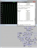
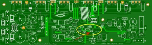
Below is the Sprint output as it is. I have added the clamp diode , it is designated as "D-BC-option" (circled in yellow).
Q10's output trace only crosses low impedance traces , the emitter resistor of Q10 (R23) and the TMC feedback trace (where C7-8 and R24 meet) ... also low impedance - as it is the main output > R24.
The Diode (D-BC-option) jumps the regulated V+ rail to the base of Q9. So , we have the V+ separating low and high imp. .... UNLESS Q10 saturates.
With the best diode (very low reverse leakage) one should not realize the diode's effect during normal use.
An SMD device could be used on the topside of the board with a little skill at soldering wires on the device.
I decided to not use SMD pads to keep the base trace of Q9 "clean" and separated from the VAS by the V+ trace.
Any comments and suggestions are HIGHLY welcome - this amp is for the community.
OS
They are all gone! ... Variac has messaged me for the updated boards.
I explained I wanted to run the output (the final V2.4) - through the forum to look for mistakes and to verify the addition of the baker clamp diode.
Below is the Sprint output as it is. I have added the clamp diode , it is designated as "D-BC-option" (circled in yellow).
Q10's output trace only crosses low impedance traces , the emitter resistor of Q10 (R23) and the TMC feedback trace (where C7-8 and R24 meet) ... also low impedance - as it is the main output > R24.
The Diode (D-BC-option) jumps the regulated V+ rail to the base of Q9. So , we have the V+ separating low and high imp. .... UNLESS Q10 saturates.
With the best diode (very low reverse leakage) one should not realize the diode's effect during normal use.
An SMD device could be used on the topside of the board with a little skill at soldering wires on the device.
I decided to not use SMD pads to keep the base trace of Q9 "clean" and separated from the VAS by the V+ trace.
Any comments and suggestions are HIGHLY welcome - this amp is for the community.
OS
Attachments
Great amplifier design spoilt by disasterous Twist-A-Plot documentation & board print
Nobody commented? Unbelievably, it is up to me, so here goes with that. . .
Yes sir. I had some ideas in Feburary, but they were not my own ideas, rather a collection of build tweaks that were popular or helped. They're at post#908 on this same thread.
That information needs inspected.
I tried my best but was confused.
There some different options and there is also an attempt to constrain the dials to block the optional explode settings, but I do not know if the schema shown does it well enough. I also tried to make sense of the luxeman zener confusions area of the schema, but could not make any sense of that.
That post may have a mix of bad and good ideas. I hope you can extract the good ideas from it. There are a few better parts, and also there's a more appropriate nfb-shunt-cap value suited for indoor use.
Ultimately, and because of the documentation, I decided that it would be unsafe for me to purchase a Honey Badger. My troubleshooting skills are not strong enough to resolve all of the questions raised by the documentation that doesn't do much else.
Unfortunately, the documentation Prevents making a (1) optimized amplifier.
As evidenced on the threads, the main cause(s) of Honey Badger failure is unsafe Twist-A-Plot assembly manual that goes in many directions instead of one. . . and there's the misleading screen print on the board that could build more than one amplifier but not all simultaneously as it is printed, which is a misdirection.
Options are nice, but please spare a totally separate document for those.
We need a goal for the assembly manual to make one (1) amplifier start up and run on the first try. That might be an appropriate assembly manual. Please choose whichever (1) design is mostly likely to play on first go. And, then don't pollute the assembly manual with confusing mishmash options. Also, the board screen print needs focused/directed towards a goal of start up and work on the first try.
Although exploration of different options may be nice, that sort needs documented separately and at a safe distance.
The amplifier design is great. I look forward to the documentation catching up to it. I'm still waiting on an assembly manual that has a goal of working.
P.S.
Sorry if that was brutal. However, you didn't get any other input. Maybe this will do it.
I do like your design. However, I would also like to use it (but I'm frustrated by the unclear assembly documentation). See the difference?
Last edited:
I wonder if you've already seen the official build guide for the Honey Badger.
The documentation does not prevent anyone from building an optimized amplifier, it gives you options, and more options. I think what you are looking for is somebody else coming up with the optimized values and post it here.
The documentation does not prevent anyone from building an optimized amplifier, it gives you options, and more options. I think what you are looking for is somebody else coming up with the optimized values and post it here.
As for the diode thing to prevent an output from sticking: There's no need to install an extra fuzzbox when the real problem is that documentation failed to enforce the notion of valid transformer voltages, 35+35vac~45+45vac range. If someone uses a lot smaller transformer than required and causes errors, that is really not a electronic design fault, but rather it is an inaccurate build. It doesn't need a design change. However, it does reiterate the need for functional documentation. There was that difference, we do need clear notes and we don't need fuzz.
Does that help sort it?
Does that help sort it?
I wonder if you've already seen the official build guide for the Honey Badger.
The documentation does not prevent anyone from building an optimized amplifier, it gives you options, and more options. I think what you are looking for is somebody else coming up with the optimized values and post it here.
Yes sir, optimized values are expected of anything that isn't prototype/experimental status.
P.S.
I don't mean to be rude, but OStripper did ask a question and my answer was to boost the documentation quality instead of presenting a mixed slew of options. Straightforward documentation is only one answer of many possible. Consider it a wish list.
Last edited:
Yes, optimized values are pretty much expected of anything that isn't prototype/experimental status.
It was aimed to make the amp build region free so it can be built all over the world without problems in sourcing the parts
The part values were chosen because of their specifications, they weren't chosen randomly. You can argue with optimization but that's the reason for the forums. The build guides are mere "guides", though it has some "spoon feeding" factor it was not meant to babysit the builder all throughout the build.
P.S.
I don't mean to be rude, but OStripper did ask a question and my answer was to boost the documentation quality instead of presenting a mixed slew of options. Straightforward documentation is only one answer of many possible. Consider it a wish list.
I am actually taking it positively, something to think about and make build guides better and more suitable to most builders.
Though you must also understand the "universality" that a build guide must have so it can be adopted not just in one continent.
Yes sir, optimized values are expected of anything that isn't prototype/experimental status.
P.S.
I don't mean to be rude, but OStripper did ask a question and my answer was to boost the documentation quality instead of presenting a mixed slew of options. Straightforward documentation is only one answer of many possible. Consider it a wish list.
I'll respond -
As most have gone with the Zener option - that should be default.
Agreed ...
Say some do NOT have a zener handy ... just jumper C-R and use yer resister. cool ... aye...
The latest option of adding the baker clamp to the VAS should remain an option as some DIY'ers are picky. Using the best diode , I see it as good option. As with current limiting and DC protection , some audiophiles feel
that the diode would detract for the audio , is this case , use a 70v rail ..
and do not clip the amp.
As another example , C18-19 (driver shunts) are used for 2sa1837/2sc4793.
This is a "option" as these devices are very high Ft. Mje15032/33 are slower
and these are not essential.
If the options are explained concisely , the builder should then be properly educated at that point to make the decision.
If the builder cannot understand the option , perhaps the project is not for
him (her ?).
If a builder needs to know more , Doug self's book is as verbose of a "reference" as one can get. Cordell's book also uses this amp as it's main reference.
THE INFO IS OUT THERE - EVERYWHERE.
The range of options also allows you to use almost anything you have available (parts wise).
This is not a chipamp , where you can set just gain and compensation.
It can be a simple 2 transistor LPT (jumper Q3-4 and use 2 2.2k resistors) all the way to the full 6 transistor IPS(LTP/cascode/CM).
In otherwords , YOU can design your own amp ... the way you want !
A regional amp (Carlo's DX , Ebay amps) can only use selected parts , using
others would require changes in degeneration/gain to keep things stable.
With this amp , a happy medium had to be taken ... allowing for dozens of different combinations of IPS/VAS/OPS components.
Documentation is easy to update , the hardware (the PCB) has to accommodate all considerations.
OS
tony, I leave that to OS to answer as I haven't got any news for any new schematic yet... cheers
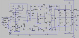
Here it is. Just the clamp diode and 1k = R24.
No big changes.
Another option was discussed (just a value change). R6 is gain ... 22k - 33k is
valid as an option.
The LM3886 also has this basic (Ri and Rfi) gain "option" ... is it's datasheet
"optimized" ? ...
They also have options for lead compensation and a pie filter for certain uses,
does this make the 3886 "hard to use" ?
By danielwritesback -There's no need to install an extra fuzzbox
That sounds like "bar talk" (ignorant statement) ...
gimme a break.The Baker clamp is the standard accepted way to deal with saturation.
Below is the schema.Originally, I was just asking for comments on the layout-
(component options) Everyone does not have the same parts !
OS
Attachments
Just solder a diode (the ones discussed) between the output side of C8 (where
C8 meets R31 and R28) and the Base of Q9 (where C7 meets Q9's base).
Cathode (the stripe) goes to the Q9 base (make sure...).
Use a little shrink wrap on the diode legs , make a neat point to point solder job
All done !
Glad to see you like the sound - it is the best for such a simple circuit.
It will totally shame a LM3886 , even with E-waste junk parts (from the dumpster) ..
OS
Last edited:
Just solder a diode (the ones discussed) between the output side of C8 (where
C8 meets R31 and R28) and the Base of Q9 (where C7 meets Q9's base).
Cathode (the stripe) goes to the Q9 base (make sure...).
Use a little shrink wrap on the diode legs , make a neat point to point solder job
All done !
Glad to see you like the sound - it is the best for such a simple circuit.
It will totally shame a LM3886 , even with E-waste junk parts (from the dumpster) ..
OS
Thanks, do I still need to change R24 to 1K5?
- Home
- Amplifiers
- Solid State
- diyAB Amp - The "Honey Badger"