Re PCB:
I would like to see an option to use larger lead spacing for C5.
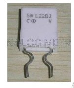
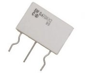
Option to use the easier to get 0R22 "cement" type resistors in the output stage.🙄
I would like to see an option to use larger lead spacing for C5.
Option to use the easier to get 0R22 "cement" type resistors in the output stage.🙄
Thanks for the responses. Whichever way the answer went, I needed the information. Much appreciated!The latest option of adding the baker clamp to the VAS should remain an option as some DIY'ers are picky. Using the best diode, I see it as good option. As with current limiting and DC protection, some audiophiles feel that the diode would detract for the audio, is this case, use a 70v rail. . . and do not clip the amp.
I like the latter option of tall rails. In that case, the Honey Badger is a lot more powerful than the speaker and thus amplifier clipping is not used. Makes sense.
Re PCB:
I would like to see an option to use larger lead spacing for C5.
Option to use the easier to get 0R22 "cement" type resistors in the output stage.🙄
+1, and also if some holes can be made larger to ease insertion of some parts around power resistors and supply caps..
Attachments
Thanks for the responses. Whichever way the answer went, I needed the information. Much appreciated!
I like the latter option of tall rails. In that case, the Honey Badger is a lot more powerful than the speaker and thus amplifier clipping is not used. Makes sense.
I wasn't mad , but I had to explain "why".
The documentation should be updated. I wrote the preliminary standard and "options" text.
The options text basically explains how each section works and gives you all the choices. Some do not like choices and would prefer others to make them .. I understand. So .... a default " build it this way or die" guide is for them.
The guide Jo Jo made is excellent and professional , perhaps we could get together and update it.
OS
PCB
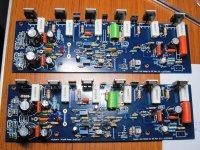
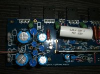
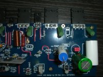
Looking at the above photo - it would help if the lead spacing for the 0.25/ 0.5 Watt resistor is increased.
Looking at the above photo - it would help if the lead spacing for the 0.25/ 0.5 Watt resistor is increased.
+1, and also if some holes can be made larger to ease insertion of some parts around power resistors and supply caps..
I did that. Some said the large diodes and some transistors were tight.
I researched all the caps, transistors , diodes and made the hole pitch at least .15mm larger than the largest expected leads.
C5 = I will do it - even make it multi pitch ! (3.5 + 5mm).
I really would like to make 25mm emitter resistor lead spacing for the "cement ones".
(below) is what I originally designed for ... (attachment 1)NOBLE 0.22/5W Resistor (5 pcs)_NOBLE_Resistor_Analog Metric - DIY Audio Kit
Also... 3W ceramics can fit the badger's 12.5mm LS.
The issue of 25mm spaced devices is that you would need to run the output bus half way (down the middle of the board).
Then you would either have to migrate some of the circuit into the section of the board that has the high current rail traces or the other OPS signal paths.
It's best to keep these small signal /high impedance sections far away from the currents.
The old amps used those 25mm monsters (attachment 2) , as most had separate OPS boards.
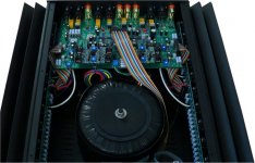
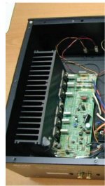
New ones use either the single noble's or the dual ones. (below attachment 3+4).
Attachments
Last edited:
Looking at the above photo - it would help if the lead spacing for the 0.25/ 0.5 Watt resistor is increased.
Which ones ? .... R- XX ??
OS
Just noticed AJT's badger's ... I want mine to look that good !! (much envy)😀
They look really good w/ 25mm emitter's ... but those 12.5 zoble resistors would be the cat's meow...
OS
They look really good w/ 25mm emitter's ... but those 12.5 zoble resistors would be the cat's meow...
OS
PCB
Many thanks for the pitch increase!
As for the 5Watt resistors I'll have to bend the leads and make them fit as in the photo.😱
Ok ...
C5 + R23 + R27
C5 = more room and multi-pitch.
R23/27 = 2mm greater lead spacing.
OS
Many thanks for the pitch increase!
As for the 5Watt resistors I'll have to bend the leads and make them fit as in the photo.😱
Yeah, that's really good--A solid start would be confidence inspiring and it would promote high quality. That didn't prevent exploring mods and options afterwards.Some do not like choices and would prefer others to make them .. I understand. So .... a default " build it this way or die" guide is for them.
Great jobs guys! Its awesome to see OS & diyaudio community continue to improve the HB building experience with the circuit/pcb update. 
Some minor suggestions for the build guide update.
Provide additional info on PSU config for 4 ohm load?
Transistors matching at what voltage/current, what tolerance?
Maybe a little write up on what advantage/disadvantage on choosing the diff. options to build apart from the standard config?
Best is to include comments from a few experience builders on why they choose to build the HB with their component choices & options?
Hi guys ,I finsh a amp today.
I'm test to tp1 and tp2.
Turn on the R30 about 8mV.
And turn on it's about 76mV.
Then R53 and R54 was burn .
what happen is it??
I'm test to tp1 and tp2.
Turn on the R30 about 8mV.
And turn on it's about 76mV.
Then R53 and R54 was burn .
what happen is it??
Hi guys ,I finsh a amp today.
I'm test to tp1 and tp2.
Turn on the R30 about 8mV.
And turn on it's about 76mV.
Then R53 and R54 was burn .
what happen is it??
No fuses ? 😕
OS
Jojo would you please post up a block diagram of your amp as pictured in post 1050, that is very impressive to say the least.
Thanks
Thanks
He did not jumper C-Z/C-R , the cascode reference is "floating". 😱
Jumpering all the small signal traces was not necessary , jumpering the rail traces is optimal.
OS
Jumpering all the small signal traces was not necessary , jumpering the rail traces is optimal.
OS
Last edited:
Jojo would you please post up a block diagram of your amp as pictured in post 1050, that is very impressive to say the least.
Thanks
Sure will do as soon as I'm finished with those in my table right now. That amp build used the Speaker Protector and the Soft Start boards as well as the V2 PSU boards available at the DA Store.
That amp has survived a lot of torture, and in an operational sense, I am sick and tired of trying to destroy it. 😀
- Home
- Amplifiers
- Solid State
- diyAB Amp - The "Honey Badger"
