Mark:
Thank you for your hard work and generosity!
All:
I'm considering making a bulk purchase of Mark's H9KPXG boards and selling them at cost to members in North America. Estimated pricing and other details can be found in the Swap Meet forum at https://www.diyaudio.com/forums/swa...pxg-lv-switch-soft-start-pcb.html#post6377684.
Regards,
Scott
Looks great, angrypat! congratulations. Maybe on your next build, you might decide to offset the trafo and/or the PSU PCB by one or two ranks of holes. Accepting a small amount of asymmetry, in exchange for a lot more room to mount the H9KPXG and route its wiring.
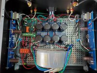
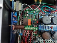
I did that on a Cordell's Super Gain Clone build, and the visible, but slight, asymmetry didn't trigger a crippling bout of Obsessive Compulsive Disorder. But you may feel differently. Click on the image to see it full size & undistorted.
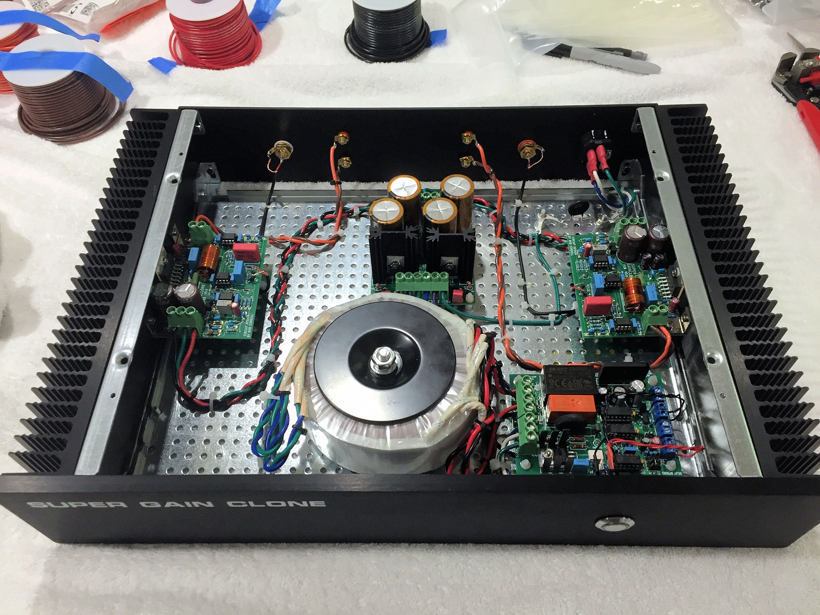
edit- forgot to say: H9KPXG board is at right front, immediately behind front panel "anti vandal" pushbutton switch. Orange colored "soft start bypass" relay is clearly visible.
_
I did that on a Cordell's Super Gain Clone build, and the visible, but slight, asymmetry didn't trigger a crippling bout of Obsessive Compulsive Disorder. But you may feel differently. Click on the image to see it full size & undistorted.
edit- forgot to say: H9KPXG board is at right front, immediately behind front panel "anti vandal" pushbutton switch. Orange colored "soft start bypass" relay is clearly visible.
_
Last edited:
Member
Joined 2009
Paid Member
Even though we, as experienced electronics builders, like to think other people can easily adapt to this way of thinking I notice this is not always the case. I fully understand your way of thinking but I grew accustomed to having to tell the answer as you just can not gain all necessary information when you missed an education and all those years of experience.
Just like the car mechanic tells me "new" things which I haven't kept up with as I just turn the key, drive and check oil level and tyre air pressure. Couldn't care less about cars as long as they bring me from A to B without trouble. Do I need all the knowledge? No. Do I like all the knowledge? Yes, but a man is limited in accepting again a new territory. Some can accept newer technology (or technology at all) quite fast and some just like the mystique in audio and will never fully grasp all the necessary stuff there is to know. They just like music and want to play it in a better way. Reading a schematic and following all the logic involved is too much for some. Many details in electronics are very strict and now of a sudden one can choose either a 16V or a 25V capacitor?! The logic that 5V won't harm any 16V or 25V cap is not self explanatory to everyone. That is why a BOM (DPL) with exact part numbers is best for those that have doubts about their own capabilities or just don't know how to reduct/deduct what can and what can not be used as alternative parts. And then, you could wait for it, people will ask if they can use parts that are not in the BOM...
To some newcomers that like this hobby very much I guess we have to tell the answers, tiring as that may be. We should be glad there are newcomers at all.
excellent post - it could be part of the Forum Constitution.
Hello
I finish my module last night. I try it with a capacitive switch from Bulgin (code mc19lobrg) and is woks nice.
I don't try yet with load, this is the next step for me.
Below i post a short video with this module working
23 octombrie 2020 - YouTube
I finish my module last night. I try it with a capacitive switch from Bulgin (code mc19lobrg) and is woks nice.
I don't try yet with load, this is the next step for me.
Below i post a short video with this module working
23 octombrie 2020 - YouTube
Last edited:
That would be a great idea! I think you might find there are far fewer choices of relays with >15 ampere contacts, when you search for double-pole relays instead of the single-pole relay used in H9KPXG.
The new relay might turn out to be housed in a physically larger package, and the necessary coil current to activate it might be a lot higher. The extra current probably won't be a problem since the AC-to-DC converter has plenty of output. But, if not, then perhaps you could change the entire circuit to operate from 12V instead of 5V. The CD4000 logic family is rated for 12V (in fact, 15V!) and the low voltage switch is almost certainly rated for it.
I don't think I will include this in the H9KPXG, but please accept my encouragement to try out the idea yourself.
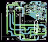
Excellent! For those who wish to investigate further, the schematic of post #214 is presented here
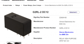
It does not include a soft start capability, and it calls for a double pole relay whose contacts are rated 8 amperes rather than 16 amps (image below). Without soft start, peak inrush current of an audio power amplifier can easily exceed 8 amps as shown in Figure 2 of the very first post in this thread.
With a tip of the hat, and a salute to cleverness, I would like to call your attention to a very cute and subtle design idea in that schematic: it DOES include a double-pole switch, in the IEC mains inlet assembly (far left). So it does conform to EU regulations. One switch is on the front panel, for the convenience of music listeners. Another switch is on the rear panel, to make the EU regulators happy. Clever and cute. And possibly a tiny bit of eff wye to the regulators.
... and ... think about it ... an unmodified H9KPXG will conform to EU regulations too, as long as you use it with an IEC mains inlet assembly which includes a double-pole switch. One switch is on the front panel and another switch is built into the IEC mains inlet. Mouser and DigiKey carry a large variety of inlets which incorporate double pole switches.
_
Attachments
Last edited:
In fact don't know much about EU regulations, indeed diy should also follow them. Just like (prefer) to cut both power lines.Probably asked because of EU regulations? Double pole power switches are also mandatory.
Which happens to be mandatory as well. It is clearly safer to cut both L and N.
Mark, you forget to mention the schematic of Hicoco also includes relay contacts in both L and N lines (not only a double pole switch) so in switched off state there will never be any voltage on the primary windings of connected transformers which is what r_jik45 meant.
Mark, you forget to mention the schematic of Hicoco also includes relay contacts in both L and N lines (not only a double pole switch) so in switched off state there will never be any voltage on the primary windings of connected transformers which is what r_jik45 meant.
Last edited:
Substitute Part for H9KPHG
Hey Folks,
Is there another film cap that will work in this position.
Detailed Parts List Line #15 22nF film cap. There are none to be had in the Good Ole USA. According to Octopart.com.
Mouser# 505-MKS4.022/630/10
Mfr.# MKS4J022202D00KSSD
On vacation this week, Gotta Gither Done
Thanks,
Ty
Hey Folks,
Is there another film cap that will work in this position.
Detailed Parts List Line #15 22nF film cap. There are none to be had in the Good Ole USA. According to Octopart.com.
Mouser# 505-MKS4.022/630/10
Mfr.# MKS4J022202D00KSSD
On vacation this week, Gotta Gither Done
Thanks,
Ty
Double check this (size, mainly) but here you go -
https://www.mouser.com/Passive-Comp...371Z1yzvvqx?P=1z0wpseZ1z0vn47Z1ywt9lg&FS=True
https://www.mouser.com/Passive-Comp...371Z1yzvvqx?P=1z0wpseZ1z0vn47Z1ywt9lg&FS=True
Yes, jean-paul, what I meant.
No softstart either, but from another thread (On/Off switch using momentary push button) I was thinking about implementing the first schematics based on the 555 (Circuits Page 9): Relay Toggle Circuit Using a 555 Timer. Made a pcb but did not try it.
If it's difficult to find a relay that fits the requirements, maybe a build with two relays could help to pass the peak inrush current.
- Home
- Amplifiers
- Power Supplies
- PCB: low voltage On-Off switch drives AC mains relay \ includes soft start .. H9KPXG