Good evening all..
Thank you all (Mark, for your design) and for everyone's excellent info on this thread.. I'm a complete noob with most of this and I have a few questions regarding substitute parts. I have a few of these boards that were gifted to me by pFarrell for my Aleph J, as well as my in the works "Salas DCG3" pre-amp. I carefully went through the build list, and got as close as possible to all the Mouser part numbers as I could.. I made some substitutions on the fly as I went through the BOM for things that were out of stock. I went through the box this evening and compared line by line each part on the BOM. Hoping those much smarter than me can tell me if what I have will work?
R1 calls for 10k/.25W.. I have 10k/ 3/5watt..
R11 calls for 180R/.25W.. My Mouser PN matches precisely but the package is labeled .6 watt.. This is the same for several resistors.. Same part number.. Interesting..
R15.. Calls for 47k/.25w.. Somehow I got 47.5k.. This is probably bafoonery on my behalf.. Will 47.5k be ok, or should I re-order that one..
C3.. Calls for 22nF @ 400VAC.. It was out of stock and I grabbed 22nF @ 630VAC.. I figure more is better right?")
I think that's all of my oddball parts.. Thanks for any guidance.. Wanted to check before starting to solder things in.. Thanks all very much, and I apologize in advance for the noob questions!
Cheers all!
John
Thank you all (Mark, for your design) and for everyone's excellent info on this thread.. I'm a complete noob with most of this and I have a few questions regarding substitute parts. I have a few of these boards that were gifted to me by pFarrell for my Aleph J, as well as my in the works "Salas DCG3" pre-amp. I carefully went through the build list, and got as close as possible to all the Mouser part numbers as I could.. I made some substitutions on the fly as I went through the BOM for things that were out of stock. I went through the box this evening and compared line by line each part on the BOM. Hoping those much smarter than me can tell me if what I have will work?
R1 calls for 10k/.25W.. I have 10k/ 3/5watt..
R11 calls for 180R/.25W.. My Mouser PN matches precisely but the package is labeled .6 watt.. This is the same for several resistors.. Same part number.. Interesting..
R15.. Calls for 47k/.25w.. Somehow I got 47.5k.. This is probably bafoonery on my behalf.. Will 47.5k be ok, or should I re-order that one..
C3.. Calls for 22nF @ 400VAC.. It was out of stock and I grabbed 22nF @ 630VAC.. I figure more is better right?
I think that's all of my oddball parts.. Thanks for any guidance.. Wanted to check before starting to solder things in.. Thanks all very much, and I apologize in advance for the noob questions!
Cheers all!
John
Last edited:
You’re fine to use higher wattage resistors, just make make sure there’s enough room. Things get kind of tight with the “soldiered” resistors. All your other parts are fine as well.
Kevin,
Thanks very much for looking at my list! This is a great group of folks for sure.. Time to fire up my soldering iron!
Cheers!
j
Dear Mark Johnson and all other Forum Members who might help me,
I've built the 230VAC Version of you Board with the Mouser Parts list supplied on Page 2 of this thread. Now I've got the problem that the Board isn't working for me.
I've measured everything on the low voltage side of the board and it seems everything there is working like it's supposed to do. The problem is, the mains voltage is always on the output. I've attached a Transformer-based 5VDC PSU and when switching on the AC Mains switch on the AC inlet, mains voltage is immediately applied to the transformer and the PSU Output. When using the momentary button for the first time you can hear the relay switching after the delay. Mains voltage is still applied. When using the momentary button a second time you can hear the relay switching but mains voltage is still applied and of course it will only turn off if I'm using the switch on my AC Inlet which cuts the power supply of the board, as well as every other mains voltages.
I've got 4 boards populated and got the same problem on all boards. I am using a small 30VA Transformer. Is the mains current drawn to low for the MOC or the Triac to switch everything off?
I hope someone is able to help me or has any ideas on how to fix this.
Thanks in advance
- DosenZorn
Edit: corrected some spelling mistakes
Last edited:
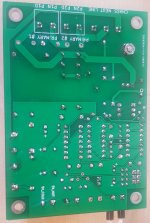
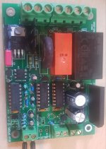
Hello, thanks for the reply. I've attached pictures of both sides to this post.
I do know that I have to insulate the triac from the heatsink and the screw. I have everything to do that and hopefully will do it immediately when I've sorted out the error with your help.
Edit: Of course I've also used the correct NTC for 230V Mains.
I do know that I have to insulate the triac from the heatsink and the screw. I have everything to do that and hopefully will do it immediately when I've sorted out the error with your help.
Edit: Of course I've also used the correct NTC for 230V Mains.
Attachments
Last edited:
Welcome, member DosenZorn!
Other members have encountered similar difficulties. Please read posts #64 thru #69 on this thread, for the problem and its solution.
I recommend that you use a mains-powered, bright light bulb (not an LED) to test your H9KPXG. Here are a couple of examples: (Amazon US link), or in the EU, (Amazon.de link).
I also recommend that you study post #396 on this thread, including the wonderful photo attached. It shows an H9KPXG under test with a proper load.
I also recommend that you read through post #1 of this thread, one more time, keeping in mind that the intended application of H9KPXG is to switch the mains on and off, for an audio power amplifier with a big, >150VA power transformer.
Thanks for the quick reply from the inventor himself.
So my assumption, that the minimal current for the Triac isn't reached and therefore it isn't switching off, seems to be the reason it isn't working for me as intended in my case. So I'll try the Optotriac alone or I'll look for a Triac with low current switching capabilities. If those aren't working I'll just remove the Triac section so the relay does the work alone.
With best regards
DosenZorn
Dear membership of diyAudio,
As usual, great thread, thanks Mark for this gift for the community! I have read through the 41 pages of posts, though I must admit it's 1:20am and I may have not absorbed all the knowledge here.
I'm looking into this as a nice front panel switch option for an external 24V PSU for my ACP+ (500mA tops), run by a 25VA 24V transformer.
Does it seem like a good idea to pair this AC mains switch with such a scenario?
I don't understand enough to know if the above comment about "audio amplifier with a big >150VA power transformer" means it won't be a good fit for my use case, or if it is just "overkill" for it?
I think it would be a nice project to make and would work nicely with a momentary power button I purchased by mistake. Obviously, I could just purchase a new button, but it's always nice to tackle a new project.
With that said, and if you guys think this could be a good match, does anyone have a PCB or two they are willing to sell to me (shipment would be to Miami, US).
Thanks in advance for any wisdom,
Best regards,
Rafa.
This PCB will work just fine as a push-on, push-off switch for the AC mains. Even when the audio gear doesn't really need soft start. Soft start definitely won't hurt a Designed-It-Yourself outboard linear power supply for an ACP+.
Soft start won't really help either. Which means: you're paying a lot of money and burning up a lot of PCB real estate, for components that you don't actually need. If that offends your inner Scotsman (or inner Dutchman (shout-out to Jan Didden!)), you could consider building a different board that has push-on, push-off mains switching, but omits soft start.
One candidate is Rod Elliott's project 166, as mentioned in the very first post of this Forum thread. No money "wasted" on a gigantic 125 Joule, 32 mm diameter, Inrush Current Limiter component made by Ametherm. No money "wasted" on a triac, optoisolator, and heatsink. Perhaps this may appeal to you on the grounds of efficiency and elegance.
I have no idea whether Rod or anyone else offers finished PCBs for sale, or Gerbers for download.
Thanks for the quick answer Mark! Yes that link is, without a doubt, exactly what I need. Both the 12V circuit as well as the mains + relay seem straightforward enough, the 12V power supply is where the appeal and the simplicity start to decay.
I may just venture a design of a PCB for those circuits with all that in mind, but I fear it may be too much for my knowledge at this point. Your 5V solution with a very simple ‘brick’ for the DC section was / is really appealing (although that particular part is not in stock in the places I could purchase and the alternative costs $16).
I’ll keep on researching, but still would appreciate it if someone has some boards available.
Thanks again,
Rafa.
Forgot the socket!?
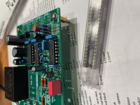
Hey all.. I've been slowly working on a few of these power boards, one for my Aleph J, and the other for Salas DCG3.. So far, so good until this evening when I forgot that U1/2/3 had sockets.. I mistakenly soldered them directly to the board absent the sockets..
Any issues with this other than an inability to remove them should one of them have an issue? Should I attempt to desolder/insert sockets and re-order U1/3/5?
Attachments
No…just run with what you’ve got.
Awesome.. Thank you Kevin.. Pressing on!
Thank you Hicoco! I have jus written to Rod Elliot asking if I can attempt a PCB with his design. It may be a simple enough project to attempt my first PCB design. Let’s see. If all falls down and doesn’t work, I’ll take you up on your offer. Thanks again!
Rafa.
Dear membership of diyAudio,
I was hoping to understand a bit how the implementation of this circuit works. I am struggling to understand the small +5V PSU implementation, particularly the chassis / earth concerns (paranoia in the words of Mark).
How and when is the BR1 useful? Since BR1 legs 3 and 2 are shorted, and 4 and 1 as well, this part of the circuit:

Would be like building this:

If this is correct, how is that not a short-circuit? I am failing to understand where would that kick in to protect and not short D-- to Chassis Earth.
Thanks for any feedback, and sorry if this, as usual, is obvious to most and just eludes me completely.
Best,
Rafa.
I was hoping to understand a bit how the implementation of this circuit works. I am struggling to understand the small +5V PSU implementation, particularly the chassis / earth concerns (paranoia in the words of Mark).
How and when is the BR1 useful? Since BR1 legs 3 and 2 are shorted, and 4 and 1 as well, this part of the circuit:
Would be like building this:
If this is correct, how is that not a short-circuit? I am failing to understand where would that kick in to protect and not short D-- to Chassis Earth.
Thanks for any feedback, and sorry if this, as usual, is obvious to most and just eludes me completely.
Best,
Rafa.
My mistake, I need to look further into this grounding circuit myself.
On the original topic, I used a switch circuit from amb.org for my first DIYAudio build (Aleph J) no soft start. You need the switch board, he has a transformer mounted board, and the power relay is mounted separately. I used a solid state relay. Between that relay, and a soft start circuit, I have a pretty loud bzzzt noise at start up. I put H9KPXG boards in M2x monoblocks, and I would use no other at this point.
I plan on mounting new amplifier boards in that amp (SissySIT R3), and will be swapping out my current switch circuit for one of Marks design.
Last edited:
- Home
- Amplifiers
- Power Supplies
- PCB: low voltage On-Off switch drives AC mains relay \ includes soft start .. H9KPXG