@Mark Johnson,
sorry for stupid questions i'm a newbie in electronic ... most only build (paint) by numbers. ;-)
Asume I would like to build a "mega" soft start box with four modules ...
- Can I use only one power switch for all modules (after removing the AC/DC modules and feed all boards from a external power supply with more power)?
- For only one P1, use output pin2 "parallel" to all modules?
- How can I make it possible that each module starts with his own delay, say module one starts immediately, the second one starts after 1 second, the third after 2 seconds and so on ...?
Hopefully you understand what I mean and thanks for suggestions.
Hi it would be possible but I would strongly suggest to design a new PCB for that and draw a schematic first. You can modify the circuit to operate from 1 power switch and even can adjust timing (P7 resistor values) or you can introduce logic with programmable sequence like Richb does. I particularly like the IR control of groups.
I don't think it is a wise idea (with regards to safety) to couple 4 of these boards to obtain the results you are after. So you could see it as a challenge to make it a complete "4 group mains voltage distributor" with mains filtering per group, separate fuses and all bells and whistles. You could also have 2 surge current limited groups and 2 normal groups for sources. If you want I can assist and sponsor some parts. I suspect many would like a complete distributor that caters for the complete audio chain instead of just 1 device. Since I build such devices I think I know what you want.
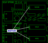
If you accept the challenge first start drawing the circuit with 40106 and copy the circuits after U3C pin6 four times and draw 4 of the mains related circuits. You can omit the 4013 if you decide on using a toggle switch (please note that most nice anti vandal switches seem to be the momentary type). If you use different value resistors per circuit for timing (P7) and don't want logic then use 47k, 100k, 150,k and 200k for a 0.5, 1, 1.5 and 2 second delay of groups. These timings are not guaranteed but approx. values. For exact sequencing you would need logic. Nothing wrong with that but hardware simplicity is appealing.
Last edited:
hello jean-paul,
Thank you for your suggestions but this is beyond my knowledge to design a new soft start module.
In the first post there is a pic withe round bubbles … there is a debounce delay (R2*C1) after switch on, default 22mSek I think.
Could this one soloution for each module?
I think for me is it easier to use these modules with a small microcontroller with „memory function“ … store last state (on / off), push button each module to toggle and a fixed delay for each module (1 - 0 sec, 2 - 4 sec, ...). For me is it equal if all modules need some time to start and are ready. Power on for all is only once the day.
Of course, seperate fuses is a must for the modules.
We could make it happen when working together. The modification of the circuit is already described. It really is not that hard but when it works as intended chances are likely that many others want one and then things get out of hand quite fast 😉 I suppose you want a sequenced delay in powering on 4 groups but simultaneous switching off? All with just 1 button?
Yup, you are German 🙂
Anyway although OP invited members to react it is probably better to start a new thread if you want to use your ideas and make a real device. Please do check the ideas of Richb in post #344. Not the same as you would like but close with enhanced possibilities (IR remote control, separate switching of groups). Maybe 2 boards could be linked (there is a Spare connector)?! This would sure cost less time than developing your own device.
Of course, seperate fuses is a must for the modules.
Yup, you are German 🙂
Anyway although OP invited members to react it is probably better to start a new thread if you want to use your ideas and make a real device. Please do check the ideas of Richb in post #344. Not the same as you would like but close with enhanced possibilities (IR remote control, separate switching of groups). Maybe 2 boards could be linked (there is a Spare connector)?! This would sure cost less time than developing your own device.
Last edited:
@Rtate, if you want an illuminated vandal switch that works with this PCB, I recommend that you buy one whose LED is rated 5V or lower. Then perform some lab experiments with the switch, plus your adjustable bench power supply set to 5V, and a current limiting potentiometer. Play with the potentiometer setting and find the external resistance value which gives you the LED brightness that you prefer. The switch itself could possibly include a resistor inside, and so your preferred brightness might need a >>ZERO<< ohm external resistor. That's why you do the experiment, to find out what's best for you.
Once you know the resistor value which pleases you, buy a fixed resistor in that value (or whatever standard value is closest) and use it for R4 on the PCB.
You might like to own a kit of standard resistor values, so you don't have to wait for a shipping-delay in those cases when you only need a resistor or two.
https://www.amazon.ca/DEYUE-Resistors-Assortment-Excellently-Breadboards/dp/B07JL6FGLM
https://www.amazon.ca/Resistor-Assortment-Resistance-Electric-Projects/dp/B07N27XYL4
This is one with only 2.5 mA flowing. Most 12V versions are even too bright on 5V... Since I detest overly bright LEDs I only use 12V versions on 5V and some then even need an extra resistor to taste. My suggestion is to choose a higher rated vandal resistent switch as modern/recent produced LEDs are insanely bright at very low current. Their sweet spot is between 1.7 and 2 mA (green/amber/red) for acceptable brightness in daylight and not blinding one in dark circumstances. For some reason they are factory set at way too much current.
Attachments

Last edited:
Thanks Guys , that makes perfect sense now.
So the 4.7K R4 is a starting point.
I don't like my led's bright either !!
So many switches to choose from sometimes I get "paralysis by analysis "
So the 4.7K R4 is a starting point.
I don't like my led's bright either !!
So many switches to choose from sometimes I get "paralysis by analysis "
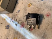
Yes , many switches to choose from but you will discover strange things when ordering the very nice looking but cheaper switches made in China. I have received switches that were 40 Ohm resistance, had steel contacts with a gold like paint etc. I sent stuff back and got my money back without much hassle but it is not good experience. The ones in post #1 are available in good and bad quality and you won't notice a visual difference!!! The blue contra-connector as in the picture is often made with steel contacts where as the switch itself may have gold plated brass contacts.
For some time now I play safe by choosing old production (but NIB) and sometimes military western stuff as quality is way better than the often very good looking but unreliable stuff. Or choose a well known brand like Bulgin and pay the high(er) price. It is frustrating when simple things like switches are unreliable certainly when removing them is a pain.
May I suggest using current as the parameter with LED brightness? Makes matters more simple. (Vbat - Vforward LED)/Iled= xxxx Ohm. It will make it simpler when having "other" voltages and of course wanting the same brightness as on other devices you built.
Last edited:
The illuminated antivandal switch I used on the front panel of my "Cordell Super Gainclone" is linked in post #16 of this thread. It's a Newark / Farnell / Element14 exclusive brand called MultiComp Pro. The particular unit I bought, sells for USD 8.60. I chose it because, among other reasons, the threaded part of the switch body is long enough to use it on an 11mm thick front panel.
I have been considering using a "trigger" circuit on my next build. One that would receive the 12v "on" signal from the pre-amp. It finally struck me (yes, I am slow that way) that a simple 12v relay be connected to that 12v, and use it to "switch" this board. The jumper would be removed for the constant type switch (not the intermittent).
Hole for the jack on the back panel, and find a relay with at least one hole to bolt somewhere.
Hole for the jack on the back panel, and find a relay with at least one hole to bolt somewhere.
I was not able to find a universally agreed upon "specification" of 12 volt trigger circuitry requirements, widely adopted by all manufacturers of all types of audio gear, in 5 minutes worth of furious Google searching.
However I did find Figure 28.6 in the 6th edition of Douglas Self's power amp textbook, "Typical 12V trigger in/out system".
After all of its protection networks, safety gizmos, and other contrivances, Self's circuit seems to draw about 6 milliamps from the 12V trigger input. Since he appears to be a relatively conservative designer (providing healthy margins-of-safety against user error or interconnection with other gear that was poorly designed), I suggest you follow his lead and design your circuits to require no more than 6mA from the trigger input.
Good news: DigiKey does have, in stock and on the shelf today, relays with 12V coils that need less than 6mA.
Bad news: they're all PCB mount, either SMD or thru hole. None have bolt holes. So you may be forced to mount your relay on a little scrap of perfboard and then bolt the perfboard to the chassis walls or chassis floor.
But -- as long as you're building a board anyway -- why not adapt and adopt Self's entire circuit with all of its safety nets? Then you could use a relay with a 5V coil and power it from the 5V Housekeeping Supply available from your H9KPXG card. Might be worth considering.
I'm just stuffing my boards now and was wondering if the chip sockets have to be mounted in a specific direction ?
They don't have any requirements, but if you purchased the ones provided in the parts list from Mark, you might consider aligning the notch in the socket relative to the proper orientation of the part on the board. This is particularly recommended if the socket will obscure the silkscreen. The notch is there, why not use it to best effect vs. potentially causing confusion (however unlikely) in the future.
Again, I agree that it's not required, but sharing an additional thought.
Again, I agree that it's not required, but sharing an additional thought.
The "notch" in the integrated circuit's plastic DIP package, tells you which of the two ends contains pin 1.
The "notch" in the DIP socket, tells you which end of the socket to plug in the pin 1 end of the IC.
I recommend you align the notch of the socket with the notch on the top silkscreen layer (white printing) of the PCBoard. This will provide a visual reminder of which way the IC should plug in.
If you're REALLY nervous about plugging in chips backwards, put a little dab of fingernail polish in the notch of each IC socket before you stuff and solder the socket into the PCB. Days later, when you insert the ICs into the sockets, you'll be able to see the notches on the sockets very clearly. They're the ends with fingernail polish!
YouTube video:
Finding pin 1 on an IC chip - YouTube
_
Attachments

Thanks Mark, I did use the force but still cant get my head around how this will connect to the H9KPXG.
2 wires to the "switch" terminals and then -5v from the 5 volt terminal ?
So I put the "+" and "A" to the switch terminals and the switch works, then I connected the "ground" copper tab to -5 volts and the led comes on but stays on in either state on or off...
I know its simple but I just can't visualize it and don't want to destroy the switch...
Last edited:
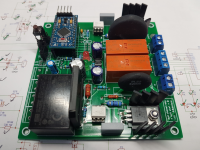
I've got the PCB for my 2-channel 'variation on a theme' built up and tested now. There were a couple of minor mistakes on the board, but nothing that could not easily be worked around.
Both the SL22 and MS32 series ICL's fit well, with plenty of clearance to the relays and heatsinks (see photo for example of both fitted).
For my application I settled on using 40 Ohm SL22's, which reduced the initial inrush current from ~30A down to ~5A. And the IR control works great too!
Thanks for the original design, and helpful pointers to get this board together.
Attachments
- Home
- Amplifiers
- Power Supplies
- PCB: low voltage On-Off switch drives AC mains relay \ includes soft start .. H9KPXG