For those using the original design, here's a change that supports the use of a switch with a 2 wire bicolor led. Replace the 40106 with a 74HC14 and then remove q1 and q2. Bride each mosfet position gate to drain. The 74HC14 have 50 ohm on resistance so they can drive the LEDs directly. For a 2 wire bicolor LED, wire between the two outputs. I reduced the resistors from 4.7k to 1k
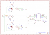
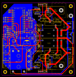
Last few tweaks to the board before getting it sent off for fabrication:
- separate control of the two channels to allow arbitrary sequencing in firmware
- brought all spare micro pins to terminals
- rotated ICL footprint so the smaller device will sit further from relays
- added earth binding post
- improved 5v supply routing
The first two changes would allow the control of up to three additional channels by connecting across to additional boards with only the high voltage parts populated, so this could be useful for sequencing up to five devices.
Attachments

Yes.....sort of......I hadn't spotted that differently rated MS32s had different diameter leads, so I've now taken the holes out to 1.3mm which I hope should be sufficient for the 1.2mm leads, thanks!Remind me -- did you enlarge the drill holes on the ICL footprint, to accommodate the bigazzs fatboy wires of the 250 Joule device? Datasheet including physical dimensions is attached to post #109 of this thread
Thanks, yes of course, I'd better get one made up and tested first so I don't lead anyone astray@richb, very nice job!
Will you be posting gerbers once completed?
Thanks
Do
Last edited:
Software.
That means, software support.
That means dealing with questions like "I've never programmed an embedded controller, in fact I've never programmed at all. Could you please walk me through your program and explain each part without using technical jargon or complicated ideas?"
and, "How would I port this code to the TI MSP430G2 microcontroller, and at the same time, add new feature X?"
Yes, a fair point I have no doubt.Software.
That means, software support.
That means dealing with questions like "I've never programmed an embedded controller, in fact I've never programmed at all. Could you please walk me through your program and explain each part without using technical jargon or complicated ideas?"
and, "How would I port this code to the TI MSP430G2 microcontroller, and at the same time, add new feature X?"
I'm hoping that by sharing on this forum, projects are seen as 'here's a thing that is designed to do XYZ, feel free to reproduce or customise as you like', rather than as an offering of a bespoke service. Then it can be used as is, or built upon based on your own ideas and expertise.
For this board in particular, I have a software that mimics your original functionality except for being dual channel (as developed for my immediate need), and I can easily add some simple configuration for sequenced startup. Beyond that, it's open for experimentation, with resonable assistance of course. I hope I'm not being too naïve!
richb, I'm pleased to see this development.
I am building a preamp in a modular fashion (volume, input selector, display, controller, etc as modules) using an Atmega328 as the controller; this MCU is handling encoders, display, and IR remote control etc.. My code is similarly modular so that it is straightforward to change, for example, just the volume board from relay based to PGA based if desired. There are quite a few examples of MCU based preamps on this forum (PIC, Atmega, ESP).
A useful module would be to be able to switch the preamp into 'standby' and for the preamp to turn on/off the power amp. For those who already have an MCU with a couple of spare pins and suitable power supplies, as is the case case for me, only a subset of what you have developed is needed.
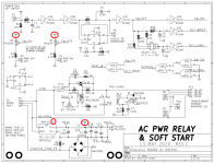
Would I be right in assuming that all I will need is the top left-hand part of your schematic (plus the mains input) and first to raise ICL then RLY after a short delay - with shut down being in the reverse order? This corresponds to the top right quadrant of your board (everything with suffix 'a').
Mark did a fantastic job of this project and I see this as an interesting development from his work. Yes, there is a question over software support - and the fact that Mark deliberately built the logic into hardware to avoid this is not lost on me. But, then again, this is DIY and people putting ideas out there, I feel, is to be encouraged. I'd be pleased to hear how you get on.
Geoff
I am building a preamp in a modular fashion (volume, input selector, display, controller, etc as modules) using an Atmega328 as the controller; this MCU is handling encoders, display, and IR remote control etc.. My code is similarly modular so that it is straightforward to change, for example, just the volume board from relay based to PGA based if desired. There are quite a few examples of MCU based preamps on this forum (PIC, Atmega, ESP).
A useful module would be to be able to switch the preamp into 'standby' and for the preamp to turn on/off the power amp. For those who already have an MCU with a couple of spare pins and suitable power supplies, as is the case case for me, only a subset of what you have developed is needed.
Would I be right in assuming that all I will need is the top left-hand part of your schematic (plus the mains input) and first to raise ICL then RLY after a short delay - with shut down being in the reverse order? This corresponds to the top right quadrant of your board (everything with suffix 'a').
Mark did a fantastic job of this project and I see this as an interesting development from his work. Yes, there is a question over software support - and the fact that Mark deliberately built the logic into hardware to avoid this is not lost on me. But, then again, this is DIY and people putting ideas out there, I feel, is to be encouraged. I'd be pleased to hear how you get on.
Geoff
I am building a preamp in a modular fashion (volume, input selector, display, controller, etc as modules) using an Atmega328 as the controller; this MCU is handling encoders, display, and IR remote control etc.. My code is similarly modular so that it is straightforward to change, for example, just the volume board from relay based to PGA based if desired. There are quite a few examples of MCU based preamps on this forum (PIC, Atmega, ESP).
I've looked through one of the modular preamp threads, very impressive! I haven't migrated to a native Atmega328 ICs yet, maybe someday.
Yes to both - this is pretty much lifted directly from Mark's design, only with direct drive of the TRIAC as well as the relay, so it should be correct although I haven't built it yet as the boards are only about to be sent for manufacture.A useful module would be to be able to switch the preamp into 'standby' and for the preamp to turn on/off the power amp. For those who already have an MCU with a couple of spare pins and suitable power supplies, as is the case case for me, only a subset of what you have developed is needed.
Would I be right in assuming that all I will need is the top left-hand part of your schematic (plus the mains input) and first to raise ICL then RLY after a short delay - with shut down being in the reverse order? This corresponds to the top right quadrant of your board (everything with suffix 'a').
Yes indeed he has, many thanks to Mark; this is a development that primarily suits my needs, but maybe of interest either 'as is' or a basis for further customisation (hardware or firmware). You could I'm sure use one of Mark's or my boards to prototype what you want, I'm happy to share one with you, or any of the design files (it's in EasyEDA), if of interest.Mark did a fantastic job of this project and I see this as an interesting development from his work. Yes, there is a question over software support - and the fact that Mark deliberately built the logic into hardware to avoid this is not lost on me. But, then again, this is DIY and people putting ideas out there, I feel, is to be encouraged. I'd be pleased to hear how you get on.
It has two channels for supplying power to two different transformers, so if that suits your setup then yes. I'll be using it to turn on a pair of power ampsCan I use this in a full "dual mono" configuration with 2 transformers ?
If you're asking about the modified board I've developed, then it has one switch, two outputsSo just "parallel" up the inputs correct ?
Last edited:
I have the 2 outputs, however with 2 separate transformers that leaves me with 4 primaries to connect.
So I'm thinking 2 primaries on each output ?
So I'm thinking 2 primaries on each output ?
@Mark Johnson,
sorry for stupid questions i'm a newbie in electronic ... most only build (paint) by numbers. ;-)
Asume I would like to build a "mega" soft start box with four modules ...
- Can I use only one power switch for all modules (after removing the AC/DC modules and feed all boards from a external power supply with more power)?
- For only one P1, use output pin2 "parallel" to all modules?
- How can I make it possible that each module starts with his own delay, say module one starts immediately, the second one starts after 1 second, the third after 2 seconds and so on ...?
Hopefully you understand what I mean and thanks for suggestions.
Let's pretend that post #357 began with the words "Dear membership of diyAudio" , namely, it was addressed to the entire community of Forum readers.
Would anyone like to reply to this inquiry?
Would anyone like to reply to this inquiry?
I am a little confused trying to select a switch for the project.
If the switch is illuminated , does it need to be a certain voltage rating ?
I see 3V, 5V and 12V rated leds on the anti vandal switches.
Or will they all work ?
If the switch is illuminated , does it need to be a certain voltage rating ?
I see 3V, 5V and 12V rated leds on the anti vandal switches.
Or will they all work ?
The schematic has the answer, see below (it's a 5v supply)I am a little confused trying to select a switch for the project.
If the switch is illuminated , does it need to be a certain voltage rating ?
I see 3V, 5V and 12V rated leds on the anti vandal switches.
Or will they all work ?
Attachments
Last edited:
- Home
- Amplifiers
- Power Supplies
- PCB: low voltage On-Off switch drives AC mains relay \ includes soft start .. H9KPXG