I'm wondering you may find something interesting if you test H2 with M/S (mid/side) encoder/decoder.")
Hi plasnu. Thanks for your note. I found on the web the operation of M/S encoder/decoder [MSED]. Its language is complex, but is interesting as it deals with processing of audio signals. Worthy of study and understanding.
Best
Anton
I have contacted Pa as requested, hopefully I am worthy
Alas, the package was rejected by Customs.
I will try again.
Experimenting with H2. Part 1; the System
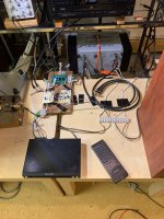
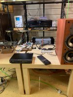
The three attached pictures show different views of the hardware which I'll be using to experiment with H2.
The middle picture shows:
1. Sony CD player as the music source. Its line level [R and L ]outputs are channeled via the the RCA Monster Cables under it.
2. Threshold S/150 power amp; 1982 or 1983 vintage. The orange cable [3 conductor] emanating from S/150 terminates in a bank of two 30,000uF capacitors; one per rail. This external bank augments the capacitance of the original and internal PSU capacitors. Makes a difference.
3. A scope to measure the Left output of H2. I need to correlate the value of this output with the graph on page 7 of the H2 article by Mr. Pass which is entitled Distortion% Vs Output Voltage. I must know the magnitude of %H2.
4. Up front is a Realistic device which reads the power output of the L channel across the Left speaker [Polk; 4 Ohms].
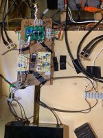
The right picture shows:
1. A top view of the H2 kit and other control electronics. The right-side proto board is a stereo buffer [to H2], and a volume level adjustment to S/150. Schematic to post.
2. The output of this stereo buffer/Volume adjument circuit feeds S/150 via 2 RCA Monster Cable cables on the right side of the view.
3. The left-side protoboard has
a. A voltage source of 2 LEDs and a Zener- connected BJT to reduce the output offset voltage of S/150 [ L ch = +45 mV, R ch = + 35 mV] to +/- 1 mV. Schematic to post.
b. An independent stereo input from SONY to the right-side proto-board [buffers/volume adjustment].
This setup will allow for an exhaustive study:
1. Direct connection from Sony to S/150. Will give me the impression of Music Fundamental [MF] plus impact [if any] of [+ DC] output offsets on S/150. Reverse the loudspeaker leads.
2. Indirect [independent] connection of SONY to S/150 via the buffer circuits. Will give me the impresion of [MF] without a DC offset at outputs of S/150. The right-side picture shows this inter-connection
3. The music impressions of the two phases of H2 with and without DC offset at the outputs of S/150.
Best
Anton
The three attached pictures show different views of the hardware which I'll be using to experiment with H2.
The middle picture shows:
1. Sony CD player as the music source. Its line level [R and L ]outputs are channeled via the the RCA Monster Cables under it.
2. Threshold S/150 power amp; 1982 or 1983 vintage. The orange cable [3 conductor] emanating from S/150 terminates in a bank of two 30,000uF capacitors; one per rail. This external bank augments the capacitance of the original and internal PSU capacitors. Makes a difference.
3. A scope to measure the Left output of H2. I need to correlate the value of this output with the graph on page 7 of the H2 article by Mr. Pass which is entitled Distortion% Vs Output Voltage. I must know the magnitude of %H2.
4. Up front is a Realistic device which reads the power output of the L channel across the Left speaker [Polk; 4 Ohms].
The right picture shows:
1. A top view of the H2 kit and other control electronics. The right-side proto board is a stereo buffer [to H2], and a volume level adjustment to S/150. Schematic to post.
2. The output of this stereo buffer/Volume adjument circuit feeds S/150 via 2 RCA Monster Cable cables on the right side of the view.
3. The left-side protoboard has
a. A voltage source of 2 LEDs and a Zener- connected BJT to reduce the output offset voltage of S/150 [ L ch = +45 mV, R ch = + 35 mV] to +/- 1 mV. Schematic to post.
b. An independent stereo input from SONY to the right-side proto-board [buffers/volume adjustment].
This setup will allow for an exhaustive study:
1. Direct connection from Sony to S/150. Will give me the impression of Music Fundamental [MF] plus impact [if any] of [+ DC] output offsets on S/150. Reverse the loudspeaker leads.
2. Indirect [independent] connection of SONY to S/150 via the buffer circuits. Will give me the impresion of [MF] without a DC offset at outputs of S/150. The right-side picture shows this inter-connection
3. The music impressions of the two phases of H2 with and without DC offset at the outputs of S/150.
Best
Anton
Attachments
Question on output impedance
The original article for the H2 used a 100Ω output resistor (R4) for a stated output impedance of around 400Ω. The updated article now uses a 332Ω resistor (R5). Does this mean its output impedance is closer to 630Ω? The text from the updated article appears to still reference the original circuit. Also, what was the reason for the increase?
The original article for the H2 used a 100Ω output resistor (R4) for a stated output impedance of around 400Ω. The updated article now uses a 332Ω resistor (R5). Does this mean its output impedance is closer to 630Ω? The text from the updated article appears to still reference the original circuit. Also, what was the reason for the increase?

If you would like a 2019 H2 generator kit, please look here -
https://www.diyaudio.com/forums/pas...9-h2-giveaway-baf-fundraiser.html#post5997001
https://www.diyaudio.com/forums/pas...9-h2-giveaway-baf-fundraiser.html#post5997001
Experimenting with H2; Part 2..Impressions
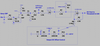
The attached is the schematic [L channel] for the audio system which I described in my previous post.
Most of this schematic is in post #390. The add-on is a circuit to reduce the power amp's output DC offset [L=+45 mV, R= +36 mV] to ~+/-1 mV. It is comprised of a string of the shown diodes plus the resistor [1 Meg] which is connected to the inverting input of the last OpAmp feeding Threshold S/150.
Essentially, the resultant H2 signal at the output of this last OpAmp is riding atop a~ [-15 to -18 mV] offset. The input of S/150 does not have a coupling cap to the preceeding stage. And thus readily allows this specific tweak. A wire shown on schematic from the proto board of the circuit can be readily connected to or disconnected [on the fly] from its destination [1 Meg] on the adjacent proto-board of the buffer/volume control OpAmp circuits.
Process conditions
1. The music output of the H2 generator was adjusted on the scope to a maximum of 1.5 Vp-p. This gave a a sweep of H2 up to ~ 1% H2 as read on the graph of page 7 in the article by Mr. Pass. Outliar peaks did emerge at ~2 Vp-p. This adjustment was done with the SONY remote commander/volume control. This adjustment was not altered when comparing H2 negative phase [H2np] with H2 positive phase [H2pp] while playing the same music/disk. It was tweaked up and/or down [counted the steps] to accomodate different disks which have variable output levels.
2. The power output of S/150 was adusted to read ~0.5 W peak on the Realistic power meter. The specific location on the schematic for this power output level adjustment is at the input of the last OpAmp; which I call Volume Control. Essentially by changing the value of the resistor which is connected to ground [82 Ohms].
Impressions.
Although my H2 generator is not calibrated per the suggestion of Mr. Pass, my impressions are commensurate with those he quoted; namely:
1. The sounds of H2np and H2pp [reverse the leads of loudspeaker] are unmistakenly different.
2. The description for the sound of [H2np] by Mr. Pass as "a deeper soundstage with improved localization than otherwise" is accurate. It is also a soothing and a calming event with each disk I listened to. Preferred
3. The description for the sound of [H2pp] by Mr. Pass as "in your face with enhanced detail" is also accurate. It was a bit louder than [H2np] to my hearing, hyper and aggressive. Its soundstage was a flat brick wall. Not preferred.
Effect of Output DC Offset of S/150 on the sounds of H2.
Maybe, I need to study more. Still, take note of the DC offset at the loudspeakers. If positive in value like S/150 has, it'll move out the cone of the DC-coupled woofer. But this same positive DC offset of S/150 will pull in the cone of the woofer when reversing the loudspeaker leads to compare the H2s. This is asymmetry in each situation and can synthesize its own H2. A DC offset of +/- 50 mV may seem trivial on paper; but its effects may not be.
Drive one loudspeaker with [H2np] and the other with [H2pp].
Gave a sound which was totally different from that of each of the H2s and the music fundamental [MF]. It was literally airy/fuzzy and floated like a wide fog above the loudspeakers. A great match in the H2 performance of the L and R channels in the H2 kit will be preferfed in this experiment. But note that this resultant sound from this test does suggest, and/or confirm that the sounds of [H2np] and [H2pp] can only be intrinsically different. Otherwise the resultant sound will default to that of [H2np] or that of [H2pp].
My studies will continue by using the same audio set up; using other loudspeakers. Fascinating, fun to me and easy to do.
Best
Anton
Attachments
Last edited:
In the meanwhile I got another kit, so I'm leaving my slot to someone else who's interested.
1 - craigtone
2 - etinsley
3 - jims
4 - sampsonite
5 - cpcornell
6 - dBel84
7 - R.K. Rønningstad
8 - plasnu
9 - DIMDAS
10 - BJager
All kits spoken for. All kits going to the USA are going out today. The 2 kits in Europe check your PM for shipping costs.
In the meanwhile I got another kit, so I'm leaving my slot to someone else who's interested.
1 - craigtone
2 - etinsley
3 - jims
4 - sampsonite
5 - cpcornell
6 - dBel84
7 - R.K. Rønningstad
8 - plasnu
9 - DIMDAS
10 -
Hello!
I purchased a kit last week, and I would like to offer my spot to another interested party.
Thank you,
dim
Hello!
I purchased a kit last week, and I would like to offer my spot to another interested party.
Thank you,
dim
All kits claimed again
Hi Nelson,
I received the kit today in the European round of giveaways organised by Max, thank you for your generosity.
I've never heard a tube amp, I've had no interest in them and come from the 'reproduction faithful to the source' camp for the most part, although I have used tone controls and DSP, so I'm no absolutist. Having this available at the very attractive price means I can play around and see what the fuss is about with these 2nd harmonics.
I'm looking forward to it!
Cheers
Neal
I think this short thread is of general interest for the members receving a H2 kit soon:
An H2 Build Walkthrough
An H2 Build Walkthrough
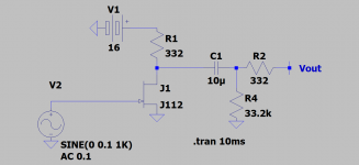
The attached LTSpice schematic simulates the performance of J112 NJFET operating as an H2 negative phase [H2np] generator per its description by Mr. Pass.
The graph of [Vout] versus Time clearly shows this signal is [H2np]. The absolute value of the positive voltage peak referenced to common is slightly less than [~732 mVp] that of the negative valley [~-747 mVp].
Voltage gain is ~7.5 and H2 is ~40 dB below the Fundamental.
40 dB = 20 Log R. Thus R = 100 which is the voltage ratio of the Fundamental to its H2. Thus [1 V/101 V] times 100 = 0.99% H2; to connect with the distortion graph on page 7 of the article by Mr. Pass.
Best
Anton
Attachments
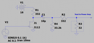
Mr. Pass wrote on page two in his article: H2 Harmonic Generator-DIY Version 1; "I don't think it can get any simpler or cheaper". True, and so are the following simplest applications which are shown in the attached schematic.
1. The actual music condition was a maximum [1 Vp-p; via scope] at the drain of the L channel JFET.
2. Added an external 32 Ohm resistor in series with the 332 Ohm resistor which is internal to the kit; so as to make a voltage divider. Vout to the Threshold S/150 power amp is taken across the 32 Ohm resistor.
3. I used my 32 Ohm Grado headphones instead of the two 32 Ohm resistors. A headphone is a Full Range [FR] driver. It has an impedance curve as a function of frequency which is like that of a woofer; maybe more level at the higher frequencies. This H2 JFET circuit is a current source amp [CSA], and is suitable to drive my headphones directly. Mr. Pass has articles on his FirstWatt website which discusss driving [FRs] with [CSA].
4. Spice simulation showed the gain of this simple circuit to be ~ one half the unloaded one. H2 is still 40 dB below the fundamental.
Best
Anton
Attachments
Last edited:
H2 Orginal Noise?
I built the H2 Ver1 into a build box with external voltage meter and adjustment pot looking forward to what it could add to my system. Had some fellow listeners over to give it a run. I should mention that system is:
Mytek Manhattan II -> Custom LDR pre -> H2 -> XA60.8s -> Martin Logan CLX Art
First thing we notice was significantly warmer sound particularly with female vocals. Also more bass and lower midrange. No loss in detail, just overall more engaging sound.
Only drawback is that even without music playing there was a noticeable low level buzz in the background which disappeared when H2 was removed from the chain.
I know that Nelson indicated that the LM317 regulators are not the quietest. I am aware that there is a Ver2 which may have addressed this noise issue with increased filtration but would like to know if filtration could be added to my Ver1 since I would really like to have it back in the system.
Happy Holidays and Listening to all!
Yes, and I have promised this to another DIYer, so I'll put it on the list.
I knew you had me on the list but figured there might be others given the number of boards you generously distributed, hence the post.
Thank you as always!