I can see you have the fets correct. So now all you need to do is connect the OV lead of your DMM to a power supply GND point and with the positive DMM lead and a schematic and the pcb layout drawing work your way through the circuit comparing the same point on each channel and write the voltage down on the schematic as measured for each channel.
At some point you must see a voltage difference highlighting the area on the dead or faulty channel as to where the fault lies.
Your soldering looks Ok, but it might be a simple bad solder joint - also did you measure all resistors with the DMM before soldering them to the board?
Good luck with it.
Gary..
Last edited:
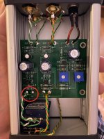
Simple mistake and will cause no component problems at all - well spotted. You can fix that from the top of the pcb without the need to pull the board out of the enclosure.
NP has confirmed to add a 10K to 50K audio taper volume pot on the input and also to leave the input resistor values the same as the schematic, for those wanting to use the H2 as a line stage pre amp with adjustable 2nd harmonic tone.
Thanks Gary. Good to know.
In addition to the wiring error discovered above I found the white wire connecting the centre pin of the pot to the board input is broken.
I’d suggest if anyone else is planning to use this Hammond case they should use more flexible hook up wire. To slide the lid in and out one end plate needs to move down. This has caused my cat6 solid core wire to fatigue and break where it’s been bent before.
1 - craigtone
2 - etinsley
3 - jims
4 - sampsonite
5 - xhumari
6 - cpcornell
7 -
8 -
9 -
10 -
And adding myself
I would like to get one. Thank you!
Morning Roo2,
Yes always a problem with very thin cross sectional area CAT type wire. I use very flexible silver plated, multistrand Teflon insulated mil spec wire for input wiring from RCA sockets to input selection, pots and onto the PCB. You can twist it very well and tightly without damage and it also does not melt the insulation when you solder the wire ends.
It is harder to strip however, but RS sells a handy PTFE insulation wire stripper that is adjustable to suit the wire size.
You can usually pick up offcuts in various sizes, lengths and colours from US based ebay sellers. It is too expensive to buy here.
Looking forward to any comments you might have when listening to music through the fully functioning H2.
Have a good day.
Gary..
Experimenting with H2 music
The results I reported in post#351 suggested a slight mismatch of %H2 between the L and R channels. The Left channel has a higher magnitude of % H2; numerically shown as 1.08 and 1.04 for L and R respectively.
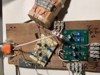
The attached is a picture of the prototype for the schematic I posted earlier. The woodblock [at the top of the view] has the independent connections of the phones in the Grado Labs headphones. The leads of each phone are connected to deliver H2 negative phase [H2np]. I streamed YouTube music via the headphones output of the hp laptop.
A revealing experiment
1. The output of [H2PV1] was adjusted to a maximum of 0.5 V peak to peak [0.18 Vrms]. The graph on page 7 of Mr Pass' article [Distortion% VS output Voltage]; showed ~0.3% H2. I used the scope to enforce this output level of [H2PV1] by displaying it in real time.
2. Started listening to [H2np] via the headphones. As the music played, I reversed the leads of only the Left channel. Got a totally different sound.. Please follow this situation:
2a. The R ear/channel operated [H2np], and the L ear/channel opereated H2 positive phase [H2pp]. My brain suggested that I am now hearing the Music Fundamental [MF].
3. I repeated steps 2 and 2a; but now I reversed the leads of the R channel. The difference between the two sounds was less pronounced than in the earlier case. The slight mismatch in the % H2 between R and L channels is responsible. It suggested that the sound of R channel was closer in character to that of [MF].
I next listened to a YouTube music video which is entitled " Take a tour of Nelson Pass' listening room" The voice of Mr Pass [especially] and Mr. Guttenberg were the music to my ears.
I repeated the above experiments; meaning one ear received [H2np] andthe other ear got [H2pp]. Got the same differences in their sound impressions. Repeatable.
The punch lines.
1. The above experiments were done by using headphones which have independent leads.; but may not be as meaningful with loudspeakers; because the bass is expected to be attenuated and/or lost. I'll still do this experiment and report back.
2. I believe that my brain reconstructed [MF] from the simultaneous use of [H2np] to one ear, and [H2pp] to the other. Revealing?
Best
Anton
The results I reported in post#351 suggested a slight mismatch of %H2 between the L and R channels. The Left channel has a higher magnitude of % H2; numerically shown as 1.08 and 1.04 for L and R respectively.
The attached is a picture of the prototype for the schematic I posted earlier. The woodblock [at the top of the view] has the independent connections of the phones in the Grado Labs headphones. The leads of each phone are connected to deliver H2 negative phase [H2np]. I streamed YouTube music via the headphones output of the hp laptop.
A revealing experiment
1. The output of [H2PV1] was adjusted to a maximum of 0.5 V peak to peak [0.18 Vrms]. The graph on page 7 of Mr Pass' article [Distortion% VS output Voltage]; showed ~0.3% H2. I used the scope to enforce this output level of [H2PV1] by displaying it in real time.
2. Started listening to [H2np] via the headphones. As the music played, I reversed the leads of only the Left channel. Got a totally different sound.. Please follow this situation:
2a. The R ear/channel operated [H2np], and the L ear/channel opereated H2 positive phase [H2pp]. My brain suggested that I am now hearing the Music Fundamental [MF].
3. I repeated steps 2 and 2a; but now I reversed the leads of the R channel. The difference between the two sounds was less pronounced than in the earlier case. The slight mismatch in the % H2 between R and L channels is responsible. It suggested that the sound of R channel was closer in character to that of [MF].
I next listened to a YouTube music video which is entitled " Take a tour of Nelson Pass' listening room" The voice of Mr Pass [especially] and Mr. Guttenberg were the music to my ears.
I repeated the above experiments; meaning one ear received [H2np] andthe other ear got [H2pp]. Got the same differences in their sound impressions. Repeatable.
The punch lines.
1. The above experiments were done by using headphones which have independent leads.; but may not be as meaningful with loudspeakers; because the bass is expected to be attenuated and/or lost. I'll still do this experiment and report back.
2. I believe that my brain reconstructed [MF] from the simultaneous use of [H2np] to one ear, and [H2pp] to the other. Revealing?
Best
Anton
Attachments
Last edited:

Mine arrived today.
Thanks Nelson.
Thinking of playing around, maybe put it between my CD and Copland, but that has 6922 pre amp valves, maybe in front of a Tri-Amp.
I’ve repaired my dodgy wiring and now have the H2 operating in stereo. My “sophisticated” listening tests with a bit of ACDC have been curtailed for the evening. I think I want to try a touch more distortion when I get the chance to reduce the input attenuation 😉
I’ve repaired my dodgy wiring and now have the H2 operating in stereo. My “sophisticated” listening tests with a bit of ACDC have been curtailed for the evening. I think I want to try a touch more distortion when I get the chance to reduce the input attenuation 😉
Hello Roo2. Will you be able to view the real time-output of H2 on the oscilloscope? Couple this view with the graph on page 7 of the Pass article "Distortion % VS Output voltage" to determine a value for %H2.
Today's digital music has a broad dynamic range. It puts % H2 all over the graph. I find that the older music [on YouTube] which predates the digital era lacks this breadth. A specific example is The Seekers song " I'll never find another you; well bounded. This great video shows the recording enginer watching the VU meters and making adjustments [level?] with his left hand.
Best
Anton
The latest ...
One more left!
1 - craigtone
2 - etinsley
3 - jims
4 - sampsonite
5 - xhumari
6 - cpcornell
7 - dBel84
8 - R.K. Rønningstad
9 - plasnu
10 -
One more left!
1 - craigtone
2 - etinsley
3 - jims
4 - sampsonite
5 - xhumari
6 - cpcornell
7 - dBel84
8 - R.K. Rønningstad
9 - plasnu
10 -
Hi Antoinel. No scope (yet). Just a broad appreciation for music, strong desire for diy and slowly failing hearing..
The latest ...
One more left!
1 - craigtone
2 - etinsley
3 - jims
4 - sampsonite
5 - xhumari
6 - cpcornell
7 - dBel84
8 - R.K. Rønningstad
9 - plasnu
10 -
Hi
If possible I would also like to have a kit.
Thanks a lot
Dim
Thank you
I received today the envelope you sent me containing the pair of FETs. Thank you.
My wife looked at the envelope and asked is he the famous Pass? I gladly replied The One and Only.
Best wishes
Anton
I will send you another pair.
🙂
I received today the envelope you sent me containing the pair of FETs. Thank you.
My wife looked at the envelope and asked is he the famous Pass? I gladly replied The One and Only.
Best wishes
Anton
All spoken for!
1 - craigtone
2 - etinsley
3 - jims
4 - sampsonite
5 - xhumari
6 - cpcornell
7 - dBel84
8 - R.K. Rønningstad
9 - plasnu
10 - DIMDAS
1 - craigtone
2 - etinsley
3 - jims
4 - sampsonite
5 - xhumari
6 - cpcornell
7 - dBel84
8 - R.K. Rønningstad
9 - plasnu
10 - DIMDAS
Hi Antoinel. No scope (yet). Just a broad appreciation for music, strong desire for diy and slowly failing hearing..
Hi Roo2. Instead of a scope, may consider assembling a kit [eBay] for an Audio LED Bargraph Display which uses LM3914. It is a fast detector of signal peaks, and is low cost. .
Best
Anton
All spoken for!
Thanks for offering up your time to help distribute these precious gifts, and thanks to Pa

.. dB
2. I believe that my brain reconstructed [MF] from the simultaneous use of [H2np] to one ear, and [H2pp] to the other. Revealing?
Best
Anton
I'm wondering you may find something interesting if you test H2 with M/S (mid/side) encoder/decoder. 🙂
Hi Roo2. Instead of a scope, may consider assembling a kit [eBay] for an Audio LED Bargraph Display which uses LM3914. It is a fast detector of signal peaks, and is low cost. .
Best
Anton
Interesting idea Antoinel.. I probably should just get an oscilloscope one day.