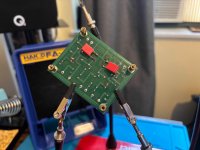
It may not be the cause of your problem but it appears to me that you have C1 and C2 capacitors installed in the wrong positions.
Check that the components, especially resistors, are in their correct positions.
Check all solder joints.
Check all wiring, especially RCA in and out.
Compare good channel to bad channel, re: components and wiring.
A comment on wiring: twist the input + and ground wires together, twist the output + and ground wires together, and twist the DC power + and ground wires together.
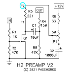
So, according to the H2 V2 document, these are the values for C1 and C2:It may not be the cause of your problem but it appears to me that you have C1 and C2 capacitors installed in the wrong positions.
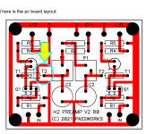
The cap at C1 (on the left in my picture) is 1,000 uF and the ones at C2 (on the right) is 10 uF. I admit I was confused to because it looks like they should be in the reversed positions based on the circles on the PCB, but the left says "C1" and the right says "C2".

You're right, it's reversed in the schematic! They should really fix that in the document, that's just incorrect. Now I'm going to have to double check the rest of the components against the schematic to make sure that the list at the bottom of the document has correct information.Must be a typo, Look at the schematic for the correct component values.
Okay so the instructions say:

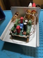
Where do I measure the DC value so that I can adjust the trimmers to set them to the value written on my bag?
Edit: tried measuring at the transistor which seems like the logical place. However, I'm getting about 4.8V on each transistor when using the D & G pins. The number on my bag, though is 10.85, but turning the trimmers all the way up doesn't get them past about 5. Note that I used the unity gain resistors instead of the ones specified in the original document, which might explain what's going on.
Last edited:
I have a feeling that the clause "... at a defined DC value which appears at T2 (referenced to ground). This value is written on the plastic bag ..."
may be significant. If so then looking around for T2 { Testpoint #2??? } might be useful?
_
may be significant. If so then looking around for T2 { Testpoint #2??? } might be useful?
_
Attachments
Oh you're right! Thanks!I have a feeling that the clause "... at a defined DC value which appears at T2 (referenced to ground). This value is written on the plastic bag ..."
may be significant. If so then looking around for T2 { Testpoint #2??? } might be useful?
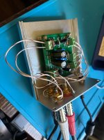
Okay, cleaned up the wire management and put the top on, this is done! I'm using it with a 12V iFi iPower SMPS.
Still playing around with this thing, but it's pretty fun. The positive phase distortion seems like it's canceling out some of the negative phase distortion with my ACP+, and also has interesting effects on my Aune S17 Pro. Still need to play with flipping the speaker terminals to get negative phase. Because the S17 Pro has single-ended and XLR inputs, I can send the XLR signal from my DAC to it straight and send the RCA signal through the H2 and thereby switch easily between one and the other and compare. I'm going to use the single-ended output from the S17 Pro to my power amp though, since Papa Pass warned that balanced connections might cancel out the harmonic distortion the H2 is adding. I'm also going to do some measurements with REW to see exactly what the device is doing in terms of distortion. (I still need to get around to posting my measurements of the ACP+, which are interesting.
I can imagine a theoretical "ultimate" H2 which would be a full preamp/headphone amp that would have a dial to change the harmonic distortion and a second amplification stage with the actual gain/potentiometer (leaving the H2 stage in unity to preserve the level of harmonic distortion) but with a switch to change from negative to positive phase distortion. I'm not skilled enough (yet) to design such a thing, but if I get there I'll post about it here.
Thank you all for your help and patience, this has been fun!