Sounds really good on the right channel. Silent on the left unfortunately.. It calibrated nicely on both channels so I suspect I’ve made a boo boo with my wiring. A job for tomorrow.
Attachments
@Roo2,
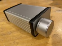
from rest of the pcb you can make a nice little label for one the the sides!
That’s a nice idea Carsten. I’ll probably remake the box ends with laser cut, neatly engraved plywood when I get the chance.
Hi Roo2, what value Alps pot is that and did you change values on input resistors at all. Also based on the NP Firstwatt article have you adjusted the trimmers as described to dial in your "preferred H2 distortion" - or in fact nulled it out.
Can't quite see from your photo's - have you got the fets in the right position and facing the right way as per silk screening - just a dumb question?
Cheers,
Gary..
Can't quite see from your photo's - have you got the fets in the right position and facing the right way as per silk screening - just a dumb question?
Cheers,
Gary..
Last edited:
Hacking commenced🙄
..Silent on the left unfortunately..
Not sure if related but when I saw the first pic, I thought R15 & R16 look a little close to the edge (possibly could contact the chassis). {Edit: probably not because those are part of the voltage regulator, but something to look out for anyway.}
Easy test is to take the board out of the main chassis and run it on the (non-conductive) bench.
Good luck, hopefully it is something simple! 🙂
Last edited:
Hi Gary. It’s a 50k Alps RK27. No change to input resistors. Should I? Sounds great on the right..Yes, I’ve set distortion to ~1% on both sides using the trimmers, measuring voltage at T2 as prescribed. Everything ok before hook up wiring.
I’d say I’ve a short in the hook up wiring somewhere. I’ve used cat6 wire and the insulation melts easily.. A job for tomorrow.
I’d say I’ve a short in the hook up wiring somewhere. I’ve used cat6 wire and the insulation melts easily.. A job for tomorrow.
Sounds really good on the right channel. Silent on the left unfortunately.. It calibrated nicely on both channels so I suspect I’ve made a boo boo with my wiring. A job for tomorrow.
Poor solder joint? I used a magnifying lens which showed me a loose Gate solder point. May jiggle the FET gently to hear the cure.
1 - craigtone
2 - etinsley
3 - jims
4 - sampsonite
5 -
6 -
7 -
8 -
9 -
10 -
I am hoping this is how you want to track who is interested.
Thanks.
2 - etinsley
3 - jims
4 - sampsonite
5 -
6 -
7 -
8 -
9 -
10 -
I am hoping this is how you want to track who is interested.
Thanks.
1 - craigtone
2 - etinsley
3 - jims
4 - sampsonite
5 - xhumari
6 -
7 -
8 -
9 -
10 -
Adding myself 🙂
2 - etinsley
3 - jims
4 - sampsonite
5 - xhumari
6 -
7 -
8 -
9 -
10 -
Adding myself 🙂
Experimenting with H2.
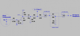
The attached schematic is a prototype sound system [for 1 channel] which incorporates therein H2 Preamp V1 [H2PV1]. Please note:
1. What is [Vin]? It is the headphones' output of a Marantz CD player. The level or volume of [Vin] is controlled with a pot which is outside the CD player. [Vin] is/contains the Fundamental frequencies of this music.
2. [Vin] emanates from a voltage source amp inside the CD player. I can readily listen to the Music Fundamental [MF] for comparison with the output at the right end of the schematic. The subjective sounds from [MF] and H2 are different. I equalize the amplitude of [Vin] and [H2 V] to ~ 50-100 mVp-p by using the scope.
3. The output of [H2PV1] is adjusted with the CD's volume pot to a value of [~ 3 Vp-p]; by using the scope. This high output level assures me that the FETs are generating up to 1% or more of H2. Page 7 in the H2 article by Mr. Pass shows a graph which is entitled "Distortion% VS Output Voltage". This graph is the basis for enriching [MF] with a substantial H2 level to hear its effects.
4. The output of [H2PV1] is buffered with the OpAmp.
5. The output of this first OpAmp [~3 Vp-p] is lowered by using the resistor string [10K in series with 300 Ohms] which functions as a volume control.
6. This attenuated voltage is buffered by the following OpAmp. Its output [H2 Vout] is now ready to drive headphones or a power amp. I emphasize that this attenuated signal [H2 Vout]; say to drive my headphones [~100 mV p-p max] contains ~1% H2 or [1 mVp-p].
7. I had cut the plug to my Grado Labs headphones so as to separate the common "ground line" they share. Each phone is independent of the other. Why? A degree of freedom which allows me to"reverse its leads" at the ouput of the last OpAmp to compare [up close] H2 negative phase [H2np] with H2 positive phase [H2pp].
8. The verdict is [H2np] sounds different from [H2pp]; along the same subjective impressions described by Mr. Pass in his article. There is no difference in perceived frequency response; its just both sounds have a different and distinct character; each of which was fully satisfactory to me.
9. I taught my hearing the sounds of [MF, H2nP and H2pp]. I listened sequentially for ~30 minutes each. I listend to the same music before and after the switchovers; because it is freshest in memory.
10. I have three different and fully acceptable-sounding audio systems. It is the prototype system of the attached schematic.
Best
Anton
Attachments
Last edited:
1 - craigtone
2 - etinsley
3 - jims
4 - sampsonite
5 - xhumari
6 - cpcornell
7 -
8 -
9 -
10 -
And adding myself
2 - etinsley
3 - jims
4 - sampsonite
5 - xhumari
6 - cpcornell
7 -
8 -
9 -
10 -
And adding myself
Hi Roo2,
50K for the pot should be fine, if you look at posts #376 and #377, I would follow the advice in #377. If it all adjusts fine and you can measure and adjust the voltage at test points as per the instructions, then you are probably correct in what you say about a problem with the wiring from the pot. Let us know how you go. I also would just check what Avtech also mentioned, make sure no component lands or solder is shorting to the case.
Cheers,
Gary..
Hi Roo2, also just had a response from NP to advise that a volume pot with value 20K to 50K is fine, on the front end of the H2.
Regards,
Gary..
Regards,
Gary..
1 - craigtone
2 - etinsley
3 - jims
4 - sampsonite
5 - xhumari
6 - cpcornell
7 - dBel84
8 -
9 -
10 -
And adding myself
I would be interested too.. dB
This is going to be great, I had been looking at laying this out on perfboard which usually ends in a mess when I do it.
Thanks NP for sharing the rest with us.
.. dB
Thanks NP for sharing the rest with us.
.. dB
I thought it was for distribution inside the US?
If not, please consider me added to the list:
Originally Posted by cpcornell View Post
1 - craigtone
2 - etinsley
3 - jims
4 - sampsonite
5 - xhumari
6 - cpcornell
7 - dBel84
8 - R.K. Rønningstad
9 -
10
If not, please consider me added to the list:
Originally Posted by cpcornell View Post
1 - craigtone
2 - etinsley
3 - jims
4 - sampsonite
5 - xhumari
6 - cpcornell
7 - dBel84
8 - R.K. Rønningstad
9 -
10
Thanks Gary. I had the 50k pot lying around so it was a good economic option..
Yes, I’ll check for shorts, etc later. My better half had other priorities today (finish tiling the kids bathroom!)..
Yes, I’ll check for shorts, etc later. My better half had other priorities today (finish tiling the kids bathroom!)..
Good to hear your better half prioritising your Sunday. Sounds like you might be spending some time on it after dinner maybe.
Hopefully some prodding around with a DMM will highlight the issue especially when you have a working channel to compare readings.
As a double check, you do have the J112 fets as per the silk screen layout in the position nearest to resistors R2 and R7. (D S G)
Hopefully some prodding around with a DMM will highlight the issue especially when you have a working channel to compare readings.
As a double check, you do have the J112 fets as per the silk screen layout in the position nearest to resistors R2 and R7. (D S G)
