Please pause any proposed changes and do the following simple diagnosis to your system starting with LDR [Optical Volume Control]. The acronym HTI used below stands for Harmonic Technologies Interconnect. It is an optical galvanic isolator which connects any two devices.
1. The music signal currently flows from: LDR via HTI to H2 via RCA coaxial cable to XA60.8.
Actually the path that has noise is already LDR -> RCA pigtails (~8 inch star quad) -> H2 -> HTI -> 60.8
2. Instead of point 1 above, reconfigure the signal flow from: LDR via RCA coaxial cable to H2 via HTI to XA60.8. Will this kill the buzz?
Noisy config as noted in (1).
The use of TRIAD WSU240-0500 PSU in the original H2 which you have has been suggested and cleared by Mr. Pass.. Best to use it because its output is already regulated. Its specs are at the TRIAD website.
While it may be regulated it is still a SMPS.
Not sure it helps but here is link to DATA SHEET for Jameco Reliapro DFU240050F1121 Transformer ...
<https://www.jameco.com/z/DFU240050F1121-AC-to-DC-Power-Supply-Wall-Adapter-Transformer-Single-Output-24-Volt-0-5-Amp-12-Watt_174879.html>
This begs the question to users of the Original H2. Did anyone encounter any hum/buzz in your loudspeakers like in Big Guy's system.
Nelson indicates that at least one other person has this noise issue. Based on their and my note of this, he is planning increased filtration of the H2 Rev1 circuit given the known noise of the LM317.
Best
Anton
Please see my comments above.
Hello Big Guy,
Your post #275 has listening impressions for H2. It also described modifications to H2. No mention of buzz!
Your post #278 shows the enclosed H2/voltmeter build. It also detailed the modifications done on the H2 PCB. Like, removing the In/Out RCA connectors from the H2 PCB, and mounting them on the enclosure. You've also disabled the 1K pot on the H2 PCB and replaced it with an external pot affixed to the enclosure. No mention of buzz!
Your post #438 tells of you and friends listening to the system. A noise buzz became evident.
What other changes to the system have been done between posts #275 and # 438 to trigger this buzz?
Please pop the hood on the enclosure and post its picture to analyze. Did the mods done on the parent H2 PCB ferment this buzz?
I found soldering the kit parts challenging. The PCB has fine lines and small eylets which maybe delicate. I used a 20X magnifier to examine each solder joint while "jiggling" the part. I found a couple of bad joints!
Best
Anton
Please see my comments above.
Thanks for your clarifications.
Please reconfigure the interconnects to this other suggested option which was # 1:
LDR via HTI to H2 via 8" RCA pigtails to XA60.8. Will it kill the buzz?
Best
Anton
Hello Big Guy,
Your post #275 has listening impressions for H2. It also described modifications to H2. No mention of buzz!
Your post #278 shows the enclosed H2/voltmeter build. It also detailed the modifications done on the H2 PCB. Like, removing the In/Out RCA connectors from the H2 PCB, and mounting them on the enclosure. You've also disabled the 1K pot on the H2 PCB and replaced it with an external pot affixed to the enclosure. No mention of buzz!
Your post #438 tells of you and friends listening to the system. A noise buzz became evident.
What other changes to the system have been done between posts #275 and # 438 to trigger this buzz?
Please pop the hood on the enclosure and post its picture to analyze. Did the mods done on the parent H2 PCB ferment this buzz?
I found soldering the kit parts challenging. The PCB has fine lines and small eylets which maybe delicate. I used a 20X magnifier to examine each solder joint while "jiggling" the part. I found a couple of bad joints!
Best
Anton
No changes between #275 and #438...just two pairs of more "golden" ears who brought the low level noise to my attention.
Will pop the hood and take a pic.
With hood popped, I will make temporary connections with both SMPS and LRPS to check for noise.
To reconfigure system as you suggest, will not be able to use the 8" pigtails due to component placement. Will need to substitute a longer pair (e.g., potential variable).
Will be offline for a while... 😉
Hi,
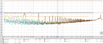
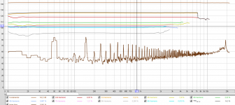
H2 mounted, with TO-220 lm317, and meanwell mini psu 🙂, here REW H2 measurement vs loopback, is that what one would expect ?
First picture is at 40 % volume, third picture is with max volume on computer onboard audio card. Too much volume, and we can change it name for H3 ^^ Noisefloor is high, but it's probably due to the long bad spaghetti jacks used crossing 220V power line.
Picture 2 is loopback of course.
I hear directly on computer to m-audio small monitors.
I have been fooled at first by what my brain wanted to think at first, but doing A/B comparison with loopback recorded songs VS recorded throught H2, it seems i don't hear that much difference. If i make volume higher, H3 become higher, and i got some nasty noise that at hear seems a bit like clipping.
I had 2,8 wrotten of my Jfets enveloppe, so i've set T2 voltage to 15,5V. I'll play again and tweak later. It's 0:43, child and wife are sleeping, and i was soldering instead of hanging laundry
Attachments

Hi Guys,
That one is perhaps more intented to Papa, but if anyone else knows the answer...
I have already a B1 Korg and love it, I played a lot with the various tunings. The H2 kit I am now building will be used to experiment with friend's around their HIFI system - and perhaps trying to convince them of the negative phase H2 benefits. I wish just to insert this little unit after their source so they can carry out A/B comparisons.
Therefore, I would like to know if I can do the same as I did with the B1K. Instead of going for the recommended 9.5V, I went for 13V, that is above null curve for B1K, thou generating directly negative H2 without the need to touch the LS cables. OK, I lose absolute phase doing so, but that's fine for a starter.
Question is: can I run safely this H2 kit at say 19V, that is higher than the null curve, and will that also result in that case in direct negative H2 generation (well noting it will stay negative as I won't reverse LS polarity, and well noting I lose absolute phase)?
Many thanks for your help
Claude
Hi,
H2 mounted, with TO-220 lm317, and meanwell mini psu 🙂, here REW H2 measurement vs loopback, is that what one would expect ?
First picture is at 40 % volume, third picture is with max volume on computer onboard audio card. Too much volume, and we can change it name for H3 ^^ Noisefloor is high, but it's probably due to the long bad spaghetti jacks used crossing 220V power line.
Picture 2 is loopback of course.
I hear directly on computer to m-audio small monitors.
I have been fooled at first by what my brain wanted to think at first, but doing A/B comparison with loopback recorded songs VS recorded throught H2, it seems i don't hear that much difference. If i make volume higher, H3 become higher, and i got some nasty noise that at hear seems a bit like clipping.
I had 2,8 wrotten of my Jfets enveloppe, so i've set T2 voltage to 15,5V. I'll play again and tweak later. It's 0:43, child and wife are sleeping, and i was soldering instead of hanging laundry
Hi papasteack.
Please show a picture of H2; focus on its wiring and the other connections.
I understand that the music signal is fed to H2 from computer [level?]. The resultant output of H2 [level?] is sent to a sound card in computer. The output of the sound card [loopback?] is sent to the loudspeakers.
Is the output of H2 too high for the onboard sound card [overload]?
Best
Anton
Hi Guys,
That one is perhaps more intented to Papa, but if anyone else knows the answer...
I have already a B1 Korg and love it, I played a lot with the various tunings. The H2 kit I am now building will be used to experiment with friend's around their HIFI system - and perhaps trying to convince them of the negative phase H2 benefits. I wish just to insert this little unit after their source so they can carry out A/B comparisons.
Therefore, I would like to know if I can do the same as I did with the B1K. Instead of going for the recommended 9.5V, I went for 13V, that is above null curve for B1K, thou generating directly negative H2 without the need to touch the LS cables. OK, I lose absolute phase doing so, but that's fine for a starter.
Question is: can I run safely this H2 kit at say 19V, that is higher than the null curve, and will that also result in that case in direct negative H2 generation (well noting it will stay negative as I won't reverse LS polarity, and well noting I lose absolute phase)?
Many thanks for your help
Claude
I am also curious to know if i can run this off at 19V5. This means I can take any of the unused laptop adaptors and convert them into a H2 PS. :-D
Err, didn't want to change the PS specs, these would remain the same 24V... I just want to know if the unit would be able to run "above the null curve" instead of under (implying a higher voltage than intended at the JFETs) and if that would bring the expected H2s...
Anyone?
Thanks again and sorry for the hassle
Claude
Anyone?
Thanks again and sorry for the hassle
Claude
lower voltage yes if dropout voltage of LM317 is ok, H2 phase don't know alas...
Hello coolnose and dewdrop. Using a 19 V PSU instead of 24 V is a good experiment to do. It won't hurt H2, and it'll answer questions from other DIYers!
The success of this experiment is by this example for a Vpinch = 2.79 V. Will the 1 K adjusting pot be able to give a V+= 16 V as seen in the last graph of the article H2 Preamp V1 which calibrates performance to a 1% H2?
Still if this desired calibration voltage of 16 V is no met, the new voltage V+ will guide you to the new expected value of % H2 from the same calibration graph.
LM317 specs suggest that for its best regulation of Vout; its [Vin -Vout need to be equal or greater than 5 V], as coolnose suggested.
Best
Anton
Measurements on the on-board H2s PSUsPSUs
I did the experiment. I have the H2 Preamp V1 model which has an independent regulated PSU for each channel. Please track the schematic as I'll refer to specific components therein.
Case1: PSU =24.12 V; linear PSU
1. V at C5=21.87 V. It is Vin to LM317.
2. Vout LM317 at R14 or R17 = 17.0 V. Thus Vin -Vout = 4.9 V [good value for regulation].
3. V at T2 = 16.0 V for either channel. It is V+ for a Vpinch = 2.79V as read on the last graph of the article; to give my target 1% H2.
4. Vds L ch.= 5.7 V. Vds R ch = 6.2 V
5. Id L ch = 10.3 V across R3 =332 Ohms calculates to = 31 mA. Id R ch = 9.8V across R8 = 332 Ohms calculates to 29 mA.
Case 2: SMPS PSU Vout= 18.9 V It is very quiet!
1. V at C5 = 16.7 V. It is Vin to LM317.
2. Vout LM317 = 15.0V for either channel. Thus Vin - Vout = 1.7 V [very lean!]. But; Vout = 15.0 V may still be regulated because Vout SMPS is regulated.
3. V at T2 = 13.9V for either channel. This voltage generates a % H2 greater than 2% as derived from the calibration graph for T2 versus Vpinch. This high level %H2 is not recommended. Eyeballing a value gives a minimum 5 % H2.
4. Vds R ch = 4.1 V. Vds Lch = 3.7 V. Ids R ch = 30 mA, Ids L ch = 31 mA.
Conclusion. System exceeds the recommended % H2 level when using a wall-wart =19 V. Its use is contra-indicated.
Best
Anton
Hello coolnose and dewdrop. Using a 19 V PSU instead of 24 V is a good experiment to do. It won't hurt H2, and it'll answer questions from other DIYers!
I did the experiment. I have the H2 Preamp V1 model which has an independent regulated PSU for each channel. Please track the schematic as I'll refer to specific components therein.
Case1: PSU =24.12 V; linear PSU
1. V at C5=21.87 V. It is Vin to LM317.
2. Vout LM317 at R14 or R17 = 17.0 V. Thus Vin -Vout = 4.9 V [good value for regulation].
3. V at T2 = 16.0 V for either channel. It is V+ for a Vpinch = 2.79V as read on the last graph of the article; to give my target 1% H2.
4. Vds L ch.= 5.7 V. Vds R ch = 6.2 V
5. Id L ch = 10.3 V across R3 =332 Ohms calculates to = 31 mA. Id R ch = 9.8V across R8 = 332 Ohms calculates to 29 mA.
Case 2: SMPS PSU Vout= 18.9 V It is very quiet!
1. V at C5 = 16.7 V. It is Vin to LM317.
2. Vout LM317 = 15.0V for either channel. Thus Vin - Vout = 1.7 V [very lean!]. But; Vout = 15.0 V may still be regulated because Vout SMPS is regulated.
3. V at T2 = 13.9V for either channel. This voltage generates a % H2 greater than 2% as derived from the calibration graph for T2 versus Vpinch. This high level %H2 is not recommended. Eyeballing a value gives a minimum 5 % H2.
4. Vds R ch = 4.1 V. Vds Lch = 3.7 V. Ids R ch = 30 mA, Ids L ch = 31 mA.
Conclusion. System exceeds the recommended % H2 level when using a wall-wart =19 V. Its use is contra-indicated.
Best
Anton
Hello Claude. The area above the blue "null curve" of the calibration plot [T2 vs. Vpinch] is off-scale and is undetermined.Err, didn't want to change the PS specs, these would remain the same 24V... I just want to know if the unit would be able to run "above the null curve" instead of under (implying a higher voltage than intended at the JFETs) and if that would bring the expected H2s...
Anyone?
Thanks again and sorry for the hassle
Claude
I'll revert to the 24 V PSU. I'll measure the maximum value of V+ at T2 by adjusting the pots, and report.
Best
Anton
I'll revert to the 24 V PSU. I'll measure the maximum value of V+ at T2 by adjusting the pots, and report.
Best
Anton
Hello Claude. Did the above.
Maximum Vout of LM317 for Rch = 17.4V.
Maximum Vout of LM317 for L ch = 17.6V.
Maximum V+ at T2 Rch = 16.4V
Maximum V+ at T2 L ch = 16.6V
It follows that the new maximum values of T2 [~16.5V avg] put the % H2 in the [determined] area between "Null" and 1%; say an eyeball value of ~0.5%. Works if one chooses to operate the device at less than the suggested maximum 1% H2.
Next, one uses the above 0.5% H2 in the graph on page 7 of the article relating % distortion versus output voltage. It determine the working value of Vout [eyeball 0.3 V rms] for further processing.
Best
Anton
Very clear answer Anton, many thanks to you!
And happy new year as nearly there on my side of the Atlantic!
Claude
And happy new year as nearly there on my side of the Atlantic!
Claude
Very clear answer Anton, many thanks to you!
And happy new year as nearly there on my side of the Atlantic!
Claude
You are welcome and thanks Claude. Wishing you also a happy, healthy and prosperous 2020.
Anton
Happy New Year Guys.....
I've had more than one request for the information to modify the
original (more noisy) H2 (2018) so as to have the lower noise of the
later one (2019).
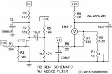
In the schematic you will see that I have split R2 into two resistors,
with the 332 ohm original value joined in series by a 33.2 ohm resistor
which goes to the supply. The other end of the 332 ohm goes to the
Drain of the Fet on each channel. The point at which these two resistors
join becomes the new T2, and this is filtered to ground with a 1000uF cap.
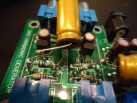
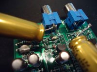
I have also attached two photos showing an actual board that I have
modified.
After this modification, the voltage at T2 should be set to the same
voltage as originally, so you want to make note of that voltage before
you start and check it again with a voltmeter.

I've had more than one request for the information to modify the
original (more noisy) H2 (2018) so as to have the lower noise of the
later one (2019).
In the schematic you will see that I have split R2 into two resistors,
with the 332 ohm original value joined in series by a 33.2 ohm resistor
which goes to the supply. The other end of the 332 ohm goes to the
Drain of the Fet on each channel. The point at which these two resistors
join becomes the new T2, and this is filtered to ground with a 1000uF cap.
I have also attached two photos showing an actual board that I have
modified.
After this modification, the voltage at T2 should be set to the same
voltage as originally, so you want to make note of that voltage before
you start and check it again with a voltmeter.
Attachments
Importance of Harmonics Phase Shift
Question on the H2 & B1K. When running simulations of these in LTSpice, I noticed that the harmonics seem to be aligned at 90 degree intervals (approximately). This doesn't appear to occur as much with other preamps and power amps I've observed in simulations.
Is this one of the factors that helps make the distortion from these devices "special"? Other than 2nd order distortion being dominant.
The phase alignment I have described is based on the peaks of fundamental as
aligned with peaks of the 2nd harmonic. "Positive phase" is where the positive
peaks of the 2nd harmonic are aligned with both the positive and negative peaks
of the fundamental, and "negative phase" is where both fundamental peaks are
aligned with negative peaks of the 2nd harmonic.
aligned with peaks of the 2nd harmonic. "Positive phase" is where the positive
peaks of the 2nd harmonic are aligned with both the positive and negative peaks
of the fundamental, and "negative phase" is where both fundamental peaks are
aligned with negative peaks of the 2nd harmonic.
Happy New Year Guys.....
Wishing you and all AudioDiyers a happy, healthy and prosperous 2020.
Anton