

I have a bunch of dual 100K linear pots laying around somewhere. Thought it would be cool to vary the signal level and thus the amount of H2 while keeping the overall gain of the circuit relatively constant. Just dial in as much H2 as sounds good.
This is what I came up with. It seems to work according to the spreadsheet I created. Haven't had a chance to wire it up and run the THD numbers.
This is what I came up with. It seems to work according to the spreadsheet I created. Haven't had a chance to wire it up and run the THD numbers.
Attachments
I strongly advise to add a capacitor from adjust to ground, following the data sheet. I never use a LM317 without that cap.
10 - 47uF is enough.
10 - 47uF is enough.
H2 Preamp V1R0 T2 Calibration
Hi all,
I've been listening to the H2 for about 6 weeks (set at 1% 15.75V for Jfet 2.76) and I decieded to try and adjust it to the NULL point (about 17.4V) but both pots max out about 16.5V. Would changing a resistor allow me to reach 17.4V ? If yes which one and what would the new value be.
Thanks
Andy
You should be able to raise the voltage by reducing the resistor in series with
the adjustment pot.
the adjustment pot.
Thank you for the reply.
I think its R13 and R16 but not 100% sure would reducing these to @ 3K give me the extra 0.9V.
Andy
I think its R13 and R16 but not 100% sure would reducing these to @ 3K give me the extra 0.9V.
Andy
It's in series with a pot that is set at 0 ohms clockwise. You can take the
series resistor to 2.2K easily
series resistor to 2.2K easily
Thank you for the reply.
I think its R13 and R16 but not 100% sure would reducing these to @ 3K give me the extra 0.9V.
Andy
Hello andy20060. I only see R13 [3.32K] in the schematic of the original H2 which has only one LM317.
I suggest that you leave R13 in place and parallel a 6.8K across its leads. The resulting value of the two parallel resistors is 2.23K; as suggested by Mr. Pass. The PCB traces are fine/delicate. I am weary of desoldering and soldering components to the PCB.
Best
Anton
Hello andy20060.
Please lookup the LM317 datasheet, and find the equation which calculates its output voltage.
The equation says that the sum value of R13 [3.3K] and the adjustment pot [max 1K] must be increased so as to increase Vo.
You have H2 V1 which has twin LM317s. It follows that the above fully applies to the branch of R16 twin [3.32K] and its 1 K pot.
Best
Anton
Hi there,
I changed R13/R16 to 2.6K which i had on hand. The max voltage @T2 went down to 14.2V .
I then added two smaller resistors in series to R13 to bring it up to 4.36K and I did the same to R16. The max volgate @T2 went up to 19V which I was then able to adjust to 17.4V .
Job Done.
Andy
I changed R13/R16 to 2.6K which i had on hand. The max voltage @T2 went down to 14.2V .
I then added two smaller resistors in series to R13 to bring it up to 4.36K and I did the same to R16. The max volgate @T2 went up to 19V which I was then able to adjust to 17.4V .
Job Done.
Andy
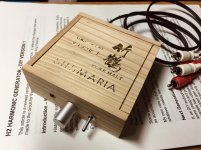
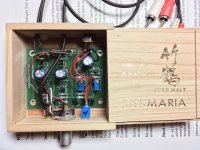

Thanks so much for posting the pictures! Gorgeous. Now, I need to get creative and see how I can nab a few boxes that my wife has set aside... 😀