@Yoshida:
Very beautiful box, and it fits perfectly for H2.
By the way, I have been able to listen to H2. To my ears, it adds a "nice coloration" just like a pair of nice sunglasses do to your eyes. You know that the " sky is not that much blue" but who cares, as long as you like it! 😉
Likewise, H2 adds a slighly euphonic character to an amp that otherwise could sound "too dry". ( I have used it with a chipamp). Tried the "phase game" and it is exactly as Nelson described it: The positive phase secon-harmonic adds euphonics, and brings some details, voices forward, just at your face. Flip the speaker connections and.. that becoming the negative phase second-harmonic, the image pulls backwards, but not only that, it widens in space. To give you an analogy, imagine a spotlight shining at you, and the same spotlight shining onto the wall and dissipating the light...
So, I have adjusted at roughly 1% and didn't try other setting. And now the caveat: I liked it most of the time, but... Not all the time. There were occasions when I wanted slighly less
second hrmonic distortion (for example when listening to Astral Projection). I disconnwcted H2, but, oh no, it became to dry again.
The idea:
How about installing a small switch, (with two pairs of contacts) that would connect suitable resistors across the trimpots?
Hence, it will be possible to choose between 1% distortion, and less than that, by flipping the switch and increasing supply voltage.
Another, slighly off topic thought: If I was to build a simplest class A amp, what would I do?
Most probably, that would be a MoFo.
But then, which preamp would I use?
Most probably ol' good Bride of Zen.
Why?
I assume that MoFo follower is mostly neutral sounding.
Then, it would take a preamplifier that would have enough gain and be able to add just right amount of second-order distortion.
And finally, a question for Nelson: Could the original BoZ preamp be dialed to provide roughly 1% distortion at some mid-volume? I guess that the easiest way would be to decrease its supply voltage, hence bias, but the question is by how much...
Regards,
Vix
Perhaps worth trying a B1 Korg, as that might bring you closer to your ideal? In my case with my set up, 0.5% H2 at 1V. Never needed to play again with the bias setting.
Although I have both the B1 Korg (as proper pre) and this little H2 (as simple sound wurzer, mainly for friends to try if they like the idea of negative H2), I must confess I haven't compared them directly yet... and anyway they aren't in the same league re parts used, nor in terms of set up (one is configured as a pre, the other not). But it could well be that the B1 Korg performs differently / better. All I can tell is that it sounds great and that it is easily tunable from negative to positive H2 even without swapping LS connections (at the cost though of absolute phase then, something you could be sensitive to or not so).
For sure Papa or other posters here that have tried both fantastic units in a similar tune and in the sale set up can say more regarding their comparative sonic vertues, so perhaps another solution emerges for you if you like the flavour and don't want to change between songs. I am just thinking loud as I use my sound wurzer indeed only for friends to try, so to say as a starter, it and if they like it I do direct them to the excellent B1 Korg kit, which I consider (perhaps wrongly) as a main dish. That's just me and convenient that way, keeping my B1 Korg at mine while I hope advertising Papa's work as deserved IMHO..
So as for me, I do like that extra flavour indeed (negative H2, not too much), and both units are thanks to Papa - I never regreted building and using them!
Claude
Last edited:
Could the original BoZ preamp be dialed to provide roughly 1% distortion at some mid-volume?
Any transistor can be dialed in for that, but many devices would find
themselves at an inconvenient operating point. In the case of the H2,
the J112 was the best part. A 2SK170 would probably have to be
operated at quite a low voltage, perhaps not enough to drive a power
amp to a decent level.
Thanks Nelson.
H2 excercise helped me understand why F2 was my preferred amplifier. I had also noticed that I mostly liked it when it was driven by just a buffer (B1) with speaker connections inversed. (I had also tried F2 with Boz and the like preamps that also invert the phase, so that the speakers were connected as usual. Theoretically, that should have sounded the same, except the difference in gain, but..it didn't, and I couldn't explain why).
Also, that's why a tube buffered GC was my preferred one...
I will add a switch to vary the H2 supply voltage, and I plan to replace the electrolytic output cap with a better one...
Retuning the Original H2
Have made the R+C additions to the original version of the H2 to provide additional noise filtration to the two channels.
Perhaps obvious but the voltage being outputted at P1 is still approximately 15V.
Do I need to check the output voltages for each channel which I originally measure at approximately 5.5V?
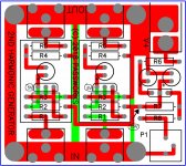
Attached is the art from the pcb. I have labeled 3 points where you
should measure approximately 5, 5, and 15 volts respectively.
Need to refresh my memory...
Given the relative difficulty of measuring the 5V outputs at the regulators as shown in the annotated schematic, can the voltage be determined at another point...the lead on R3 just below the circled 5V's?
You could temporarily solder three pieces of wire-wrap wire (insulated 30AWG) to the PCB at those points. Make each wire 10 cm long so you can use blue painters tape to affix each wire to the PCB, so that pulling on the wire pulls on the tape and not the solder joint. After the measurement is complete, cut them off or unsolder them. Or not: you may want to repeat the measurement nine months from now.
You could temporarily solder three pieces of wire-wrap wire (insulated 30AWG) to the PCB at those points. Make each wire 10 cm long so you can use blue painters tape to affix each wire to the PCB, so that pulling on the wire pulls on the tape and not the solder joint. After the measurement is complete, cut them off or unsolder them. Or not: you may want to repeat the measurement nine months from now.
On each channel you see that R2 is connected to both points of interest.
Thank you both. Class, can anyone spell "newbie"?
I had measured the voltages at the 2 R2 point at 5.44 and 5.48 and an input voltage of 15.65 which had some fluctuation.
Post modification with the recommended R&C yielded V's at R2 considerably less than the ~5.5 volts, i.e., ~4V.
P1 needed to be adjusted to 16.75V to get back to ~5.5V at both R2's.
While the P1 voltage was rock steady at the 16.75V (with a LRPS replacing the original SMPS, it seemed to take quite a while to get to "steady state" readings at R2.
Is this to be expected?
Thanks as always.
Yes, the Jfet has to warm up a little bit. In any case, you will go by the DC
values at the Drain of the Jfet.
values at the Drain of the Jfet.
Yes, the Jfet has to warm up a little bit. In any case, you will go by the DC
values at the Drain of the Jfet.
Thanks, Nelson. As long as the voltages at the Drain of the Jfet are the test points at R2 as noted above, I am good.
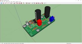
Finally got to build the H2, now waiting for the wall wart to arrive before connecting the inputs and outputs.
I think I have the most geeky Slingbox H2 in the group. ;-) Thanks Papa and Jim for your generosity.

I think I have the most geeky Slingbox H2 in the group. ;-) Thanks Papa and Jim for your generosity.
Hello Mr. Pass,
I´ve designed the H2 to be compatible with M2x mounting so I´m asking for your permission to offer, if builders interested, this board in a future GB.
If interest to low I´ll put all the manufacturing datas online so everybody could order PCB´s and built himself this excellent circuit.
JP
I´ve designed the H2 to be compatible with M2x mounting so I´m asking for your permission to offer, if builders interested, this board in a future GB.
If interest to low I´ll put all the manufacturing datas online so everybody could order PCB´s and built himself this excellent circuit.
JP