Hi X,
Is there any wrong way to install J9/J10. Mine have 3 "T"'s on one side, and on the underneath their is a round circle between the first 2 sections.
I just looked at your pics, and could not see any "T" markings, so installed with the "T"'s facing the MFets.
Also left a message on Etsy about the LED. I installed with cathode (short leg) in the square pad. Correct?
Thanks,
Myles
Hi Myles,
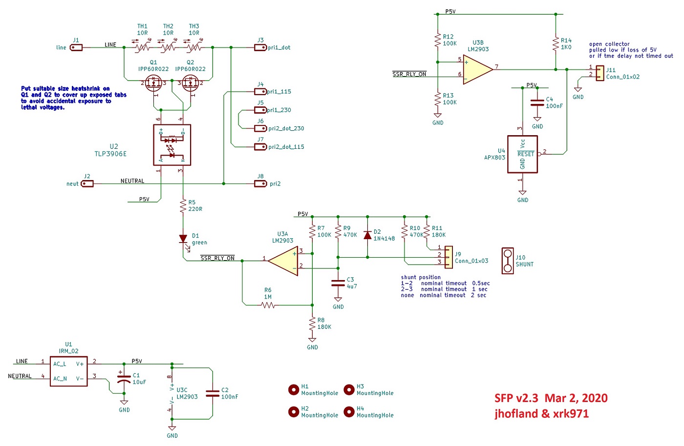
J9 and 10 are just header/jumper to select the turn on delay. Leave the jumper off (hang on one pin so you don’t lose it) for 2 second delay. The orientation of the header pins install does not matter.
Jhofland generally had Cathode of diode pointing to square pad. Easy check is to use the schematic and follow the trace. Which one goes to the comparator? That’s the one with the cathode (short pin).
Hi X, referring to pic in the FH9 thread
Yes the CMC filters for EMI from the mains. It was recommended to use 1 filter per transformer. I have the lines from the IEC module wired to each EMI filter. These are connected to the line and neutral of the SFP module. Is it a waste of money having 2 of these modules running on the mains?
I understand about the primaries, I have them in parallel and they are connected to the small connector on the left side of the picture in front of the SFP.
If I am using 2 transformers, do I need to run 2 wires from the opposite side of the connector block where the primaries are connected, to J3, J4, and J7, J8 on the SFP. Like you show for your Harmony amp.
MM
This will work. Bend the pins to fit spacing of TO-220.
250v, 80A, 16mOhm.
https://www.mouser.com/ProductDetail/IXYS/IXFH80N25X3?qs=5aG0NVq1C4zJwbKbdz1yEQ==
250v, 80A, 16mOhm.
https://www.mouser.com/ProductDetail/IXYS/IXFH80N25X3?qs=5aG0NVq1C4zJwbKbdz1yEQ==
Very cool project.
The only similar concept i've seen belongs to the Evolve amps from Japan. Integration with a DC trap allows for a single mosfet to be used.
2SK3497/2SJ618PowerAmplifier
XRK, have you thought about adding an SSR power switch to this?
The only similar concept i've seen belongs to the Evolve amps from Japan. Integration with a DC trap allows for a single mosfet to be used.
2SK3497/2SJ618PowerAmplifier
XRK, have you thought about adding an SSR power switch to this?

As I continue to go through this BOM and look at my actual PCB, I'm not sure I have the right PCB. It doesn't look like any pics that I've seen and it's labelled rev 1.0. And a bunch of the component labels on the silkscreen don't align with the BOM v2.3
I bought this from you on 12/31/2020, so from what I can see the latest version then was (and I believe still is?) v2.3.
Or maybe I just don't have the latest BOM?
I bought this from you on 12/31/2020, so from what I can see the latest version then was (and I believe still is?) v2.3.
Or maybe I just don't have the latest BOM?
Attachments
Hi Myles,
J3 and J7 are tied together and J4 and J8 are tied together. So if you have dual trafos J3 can go to J4 or J8 and J7 can go to J4 or J8.
That’s assuming your primaries are 115vac and your mains are same. If your mains are 230vac, there is a common jumper J5 and J6 to allow the two 115vac windings to be in series.
Last edited:
- Home
- Group Buys
- Soft as a Feather Pillow (SFP) SSR Soft Start Circuit GB