So, why not replace the resistors with the NTC, as suggested and then bypass it with the MOSFETs? Best of both worlds.
Rod Elliot provides some interesting insight on current inrush. Have a read here: Inrush Current
HI X, my apologies I meant the capability of max power on the inrush power resistors (25 ohms.) The MOSFETs are more than capable, of that I have no doubt.
P.S. Very nice circuit indeed, small but capable.
HI X, my apologies I meant the capability of max power on the inrush power resistors (25 ohms.) The MOSFETs are more than capable, of that I have no doubt.
P.S. Very nice circuit indeed, small but capable.
Last edited:
Hi X,
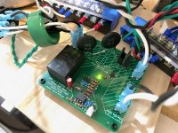
Can you advise the connection details around the connectors J3 to J8 for 230VAC supply. I think your photo's of the board are for 115VAC supply connections, thanks.
Also what is connector J11 used for? I also see you have opted for a 2 second timeout with no shunts connected to J9 in the photo's.
Regards,
Gary..
Hi Gary,
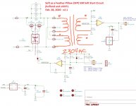
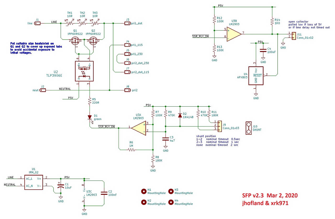
If you look at the designations on the connectors, for 230VAC mains, you want to connect your primaries in series. So Primary 1-dot goes to top pin and Primary 1 goes to the middle jumper that allows series connection of the primaries. The bottom of the middle jumper goes to Primary 2-dot and the very bottom pin goes to Primary 2 (no dot). Please see attached marked up diagram.
The other 2pin Molex is for future use with next gen speaker SSR that will have remotely controlled shutdown to disconnect speaker the instant mains is cut.
Attachments
So, why not replace the resistors with the NTC, as suggested and then bypass it with the MOSFETs? Best of both worlds.
Indeed. This was going to be my followup question as I am aware of how NTC’s work in immediate turn off - turn on situations.
Best,
Anand.
Rod Elliot provides some interesting insight on current inrush. Have a read here: Inrush Current
HI X, my apologies I meant the capability of max power on the inrush power resistors (25 ohms.) The MOSFETs are more than capable, of that I have no doubt.
P.S. Very nice circuit indeed, small but capable.
Those are 5w x 4 or 20w of dissipation. Not a large amount but fortunately, they only need to work for 2 seconds. In that amount of time, thermal issues are negligible.
For 230VAC max inrush current is 230VAC/25ohm = 9.3A. But this dissipates quickly, that is, not continuous for entire 2 second period and in fact drops to something like 50v across the resistors at steady state for a 2.5A load. That would be 100w continuous dissipation if the SSR failed to work. The resistors would probably overheat and burn up. But since the SSR conducts at 25milliOhm after 2 seconds, all is good.
Does that answer your question?
So, why not replace the resistors with the NTC, as suggested and then bypass it with the MOSFETs? Best of both worlds.
Hi BrianL and Anand,
I just rethought this whole scenario. I was wrong. You guys have a good suggestion, and here’s why.
I forgot that the SSR cuts in at 2 seconds and the NTC never heats up fully. So it retains its high R.
In the event that the SSR ever fails to conduct fully, we switchover back to operation like with an NTC. It will get hot and lower it’s R so it doesn’t burn up. We would be back to the old way of operating but it’s not a hazardous situation like having a resistor catch fire. Let me discuss with Jhofland and it may make sense to put two 8D-20 in series for 16ohms or two CL-60s in series for 20ohms. The two in series is just for extra soft start vs just one. It is a simple fix/change to the layout. I should test it out though.
Thanks!
Last edited:
You would only need to have the NTC on for a couple seconds as by then it's done its work. Then when shorted by the MOSFETs it would return to near ambient quite quickly. So, unless you're trying your best to cycle power very quickly, there's not any likely reasonable scenario where the NTC is not high-ish resistance. Also, if power is being cycled that quickly, your load (amp or whatever) is only partially discharging its supply.
Maybe Jan would care to weigh in on his design tradeoffs.
Maybe Jan would care to weigh in on his design tradeoffs.
BrianL,
Yes. I agree that NTCs here would be better since the SSR cuts in and they never get too hot.
Thanks,
X
Yes. I agree that NTCs here would be better since the SSR cuts in and they never get too hot.
Thanks,
X
Thanks X, yes. I will definitely be in for one board. I'll go to the shop and order during the week.
Regards, Kevin
P.S Though call me conservative - I will stick with resistors. Have a whole bash of 120R 10W jobs.
Regards, Kevin
P.S Though call me conservative - I will stick with resistors. Have a whole bash of 120R 10W jobs.
Last edited:
Tested SFP with 2x 8D-20 NTC
I just installed the two 8D-20 NTC's in series on the SFP. It works fine and although the warm up slightly at turn on, within a minute they are back to room tempertature, meaning that they will give 16ohms of turn on resistance the next time around. I could have used three in series and gotten back close to the original 25ohm value of the resistors. Even at 16ohms, there was absolute silence from the speakers at turn on - no thump detected.
I think we will make the design to go with 3 NTCs in series for a truly soft start board. The NTCs also provide insurance against burning resistors should the MOSFET ever fail.
Attachments
X,
I like the NTC design, to be clear for the members, I assume V2.3 is the final design that will be for sale in your Etsy shop - or will you have the resistor based V2.1 as well to pick from?
I like the NTC design, to be clear for the members, I assume V2.3 is the final design that will be for sale in your Etsy shop - or will you have the resistor based V2.1 as well to pick from?
Thanks X, all clear again.
I assume you will post a revised schematic and BOM when you find the time.
I assume you will post a revised schematic and BOM when you find the time.
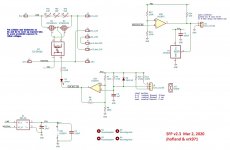
Version 2.3 with NTCs
Here is the schematic and BOM for the new version with the NTC's. This will be the final version going to production and also in my Etsy shop.
BOM:
Here is the schematic and BOM for the new version with the NTC's. This will be the final version going to production and also in my Etsy shop.
BOM:
Code:
Qty	Reference(s)	Value	Manufacturer	MPN
1	C1	10uF	Wurth Electronik	8.6001E+11
2	C2, C4	100nF	TDK	FA18X7R1H104KNU06
1	C3	4u7	TDK	FG18X5R1E475KRT06
1	D1	green	LiteOn	LTL-4236N
1	D2	1N4148	On Semiconductor	1N4148
1	J1, J2, J3, J4, J5, J6, J7, J8	 	TE Connectivity	62409-1
1	J9	Conn_01x03	Wurth Electronik	61300311121
1	J10	SHUNT	TE Connectivity	382811-6
1	J11	Conn_01x02	Molex	22-23-2023
2	Q1, Q2	IPP60R022	Infineon Technologies	IPP60R022S7XKSA1
1	R5	220R	Vishay/Dale	CCF07220RJKE36
1	R6	1M	Vishay	CCF071M00GKE36
3	R7, R12, R13	100K	Vishay	CCF07100KJKE36
2	R8, R11	180K	Vishay	CCF07180KGKE36
2	R9, R10	470K	Vishay	CCF07470KGKE36
1	R14	1K0	Vishay	SFR25H0001001FR500
3	TH1, TH2, TH3	10R	Ametherm	SL15-10006
1	U1	IRM_02	MeanWell	IRM-02-5
1	U2	TLP3906E	Toshiba	TLP3906(E
1	U3	LM2903	Texas Instruments	LM2903P
1	U4	APX803	Diodes Inc	APX803S05-46SA-7
Attachments
- Home
- Group Buys
- Soft as a Feather Pillow (SFP) SSR Soft Start Circuit GB