Thanks X, I will use J3,J4 as a pair and J7,J8 as the other pair. Also I built 4 of these for future projects, and on one of them the LED does not light. Thinking that I may have it backwards, I changed it out and wired cathode to the direction of U3 (comparator and square pad ). The led still would not light up.
I will do some continuity checks, and try to find the problem. Any idea's you can help with?
MM
I will do some continuity checks, and try to find the problem. Any idea's you can help with?
MM
If the LED doesn’t light, it means current is not running through the optoisolator. Is the on board 5vdc supply making 5v? Next is to check if the (looks like opamp) comparator is getting power. Check the pins to see if working.
Please post a nice closeup photo of the SFP that’s not working.
Please post a nice closeup photo of the SFP that’s not working.
Hi X,
Here are 2 pics


I measured 5VDC on the meanwell irm-02-5 supply.
I have continuity from Line to J3 & J7 and from neutral to J4 and J8.
I have continuity from Mfets to U2 the opto coupler.
I have continuity from the optocoupler to the LED cathode, the light goes on.
From top of C2 I have continuity to the GND of Comparator.
From bottom of C2 I have continuity to the Vcc pin of the comparator.
What I do not have is any continuity from the Line to the LED cathode (no light) using DMM, and, when I hook up mains power The led does not light either.
My R7, R12, R13 values are 64.7k, 50k, 50k rather than 100k ohms, not sure if this would cause the problem I am having.
Let me know your thoughts,
Thanks,
MM
Here are 2 pics
I measured 5VDC on the meanwell irm-02-5 supply.
I have continuity from Line to J3 & J7 and from neutral to J4 and J8.
I have continuity from Mfets to U2 the opto coupler.
I have continuity from the optocoupler to the LED cathode, the light goes on.
From top of C2 I have continuity to the GND of Comparator.
From bottom of C2 I have continuity to the Vcc pin of the comparator.
What I do not have is any continuity from the Line to the LED cathode (no light) using DMM, and, when I hook up mains power The led does not light either.
My R7, R12, R13 values are 64.7k, 50k, 50k rather than 100k ohms, not sure if this would cause the problem I am having.
Let me know your thoughts,
Thanks,
MM
Hi X,
I am using a SFP that works ( I checked the continuity using the schematic and had perfect continuity). I am hooking up my DMM to TH3 and have 1 channel hooked up. I am not getting the voltage values around 50 VAC when powering on, mine are really low. Is my delay to fast to notice or some other problem?. I remember some notes on the schematic about delay times.
Not sure if you saw my previous post?
MM
Hi Myles,
I am not sure why you changed the resistor values? All I can say is build it exactly like the ones that work and see if it helps. The 67k you changed will cause the threshold level for the comparator to switch on at a higher voltage. It may not get there.
When you say voltage at TH3 is not 50v, I am not sure what you mean. When the SFP is first powered, all the current passes through the three thermistors (NTC). After about 2 seconds, the MOSFETs conduct thereby bypassing the NTCs. At that point there will not be a voltage drop across them anymore.
Hi X,
Obviously some confusion. I did not change the resistor values, these are the in circuit values that I measured with my DMM. They were all supposed to be 100K, and I am sure that I measured them before installing. So it sounds like I need to remove them and try some different ones
In post #1, you post some pics of your meter showing the turn on voltage and in the next picture you show the voltage after the soft start has engaged. I do not see this 50V on my meter, I go to a lower voltage as in your pic. Does it happen this fast?.
Thanks for the help,
MM
Hello Kokanee,
Perhaps I can help.
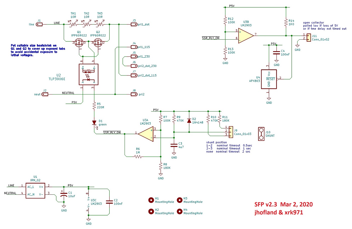
The way the circuit is supposed to work is when power is first applied the voltage at pin 3 of the comparator is higher than the voltage across cap C3 and the output of the comparator, pin 1, is not sinking current so the optoisolator won't turn on. the voltage across C3 will rise toward 5V and after about 1 second nominal it will exceed the voltage on pin 3 of the comaprator, at which time the output of the comparator will go low and turn the optoisolator on and the green LED will light.
Your symptom of LED off suggests that the optoisolator is installed backwards or there is an open connection between the opto, the LED, the series resistor or the comparator. I would check the voltages at pins 1, 2, and 3 on the comparator after a few seconds from turnon. You should see the voltage at pin 3 higher than that on pin 2 and the voltage at pin 1 a few tenths of a volt at most.
Perhaps I can help.
The way the circuit is supposed to work is when power is first applied the voltage at pin 3 of the comparator is higher than the voltage across cap C3 and the output of the comparator, pin 1, is not sinking current so the optoisolator won't turn on. the voltage across C3 will rise toward 5V and after about 1 second nominal it will exceed the voltage on pin 3 of the comaprator, at which time the output of the comparator will go low and turn the optoisolator on and the green LED will light.
Your symptom of LED off suggests that the optoisolator is installed backwards or there is an open connection between the opto, the LED, the series resistor or the comparator. I would check the voltages at pins 1, 2, and 3 on the comparator after a few seconds from turnon. You should see the voltage at pin 3 higher than that on pin 2 and the voltage at pin 1 a few tenths of a volt at most.
Thanks jhofland,
I am very new at testing, so with my DMM where would the black (com) probe attach if I was going to probe pin 1 on the comparator with the red probe.
Thanks,
MM
I am very new at testing, so with my DMM where would the black (com) probe attach if I was going to probe pin 1 on the comparator with the red probe.
Thanks,
MM
Hi MM,
Measurements are made with respect to ground/common. Among other points, pin 4 of the comparator is common, so the black lead would go there. And I would expect the voltage at pin 3 to be a bit over 3V.
Measurements are made with respect to ground/common. Among other points, pin 4 of the comparator is common, so the black lead would go there. And I would expect the voltage at pin 3 to be a bit over 3V.
Thanks, I thought that ground pin 4 would work also. I will take some measurements on my good boards and my 1 problem board. Need to rest my brain, will do in next couple of days.
Also I checked the orientation of the optoisolater and comparator with the pics that xrk has in the thread and looks the same, according to the position of the round dimples. Also performed continuity checks according to the schematic. I received the appropriate beeps on all tests
MM
Also I checked the orientation of the optoisolater and comparator with the pics that xrk has in the thread and looks the same, according to the position of the round dimples. Also performed continuity checks according to the schematic. I received the appropriate beeps on all tests
MM
Hi jhofland,
When building the SFP, I soldered all 3 pins of J9 in place. Should I remove it and only solder pin 3 lets say to get a 2 second delay. With all pins soldered, maybe it interferes with the logics?
Thanks for the help, have some duties so will do measurements on Tuesday.
MM
When building the SFP, I soldered all 3 pins of J9 in place. Should I remove it and only solder pin 3 lets say to get a 2 second delay. With all pins soldered, maybe it interferes with the logics?
Thanks for the help, have some duties so will do measurements on Tuesday.
MM
Hi Myles,
I don’t understand what you mean by “soldering all the pins” of J9? Do you mean they were hard wire jumpered all 3 together? These are 3 separate header pins. Don’t connect them for 2 second delay. Connect per the notes for 1 second or 0.5sec delay.
I don’t understand what you mean by “soldering all the pins” of J9? Do you mean they were hard wire jumpered all 3 together? These are 3 separate header pins. Don’t connect them for 2 second delay. Connect per the notes for 1 second or 0.5sec delay.
Hi X,
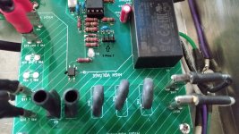
Have a look at post#103, it shows the underside of the board and how I have soldered pins 1,2,3 of J9. They are soldered independently as if soldering a transistor. No bridges between pins and no jumpers.
I will be taking voltage measurements tomorrow on the comparator on both the problem board and a good board.
Thanks for all the help so far,
MM
Hi X, jhofland,
Just to make sure: I am testing/looking at the board with the "Soft as a Feather...."writing at the btm left side. The comparator is installed with the dimple/circle on the upper right side of comparator (same as everyone's pics I have observed, writing on comparator is upside down) . From the upper right to left side of comparator I read pins 1,2,3, and Gnd. I am assuming this is correct, and I continue.
On the good board: led lights after 2 seconds of power on. With black lead on ground and the meter set to ACV, I read 4.25V. When I probe pins 3, 2, 1, the voltage drops to zero in all cases.
On the problem board: no light from led at all with power on. With black lead on ground and the meter set to ACV, I read 7.25V. When I probe pins 3, 2, 1, the voltage drops to zero in all cases.
I checked all my 3 boards where the led lights up and they operate as above with the V dropping to zero.
Is this normal?
MM
The measurements should be made using DC scale. You should see about 5V on pin 8. That is the local supply voltage. Pin 3 will be around 3VDC, and pin 2 close to 5V after the comparator has turned on. The output, pin 1 will be a few tenths of a volt.
Thanks jhofland,
Rookie me, I forgot that the Meanwell would have DC output and measurements should be DC. Man, sorry to be a pest, but sure am learning lots of what to do and not what to do. Will report back with some different readings.
MM
Rookie me, I forgot that the Meanwell would have DC output and measurements should be DC. Man, sorry to be a pest, but sure am learning lots of what to do and not what to do. Will report back with some different readings.
MM
I’m late to this game …seems these "less expensive" MOSFETS are zero in stock at all the major distributors. Another victim of the pandemic I guess. The BOM ones are $15-18 now. Ugh.
Hi folks, we found a much more cost effective MOSFET to use as the SSR here. This one is about $5 vs $12.50 for the last one. The new one is rated 650v, 44A, and 67mOhm RDson.
https://www.mouser.com/ProductDetai...I1px%2BYuwuaZKDDXAVpY0IGGVx4nLsFFbw2cmIc8hw==
These are $3.79 and good for 11 A.
https://www.mouser.com/ProductDetai...=sGAEpiMZZMutXGli8Ay4kBTMNUyJlJ9tlkh6d8taGbA=
This has 0.35ohm RDson so will heat up somewhat. Probably will need a small heatsink vs RDson 0.025 ohm ones.
You can search for “TO-220-3 MOSFET low RDson”
I am actually using TO-247 with pins bent to fit TO-220. The key is voltage able to handle mains, so 250v to 450v and low RDson. Also handle the DC current of interest.
Last edited:
- Home
- Group Buys
- Soft as a Feather Pillow (SFP) SSR Soft Start Circuit GB