I believe the way to gain confidence re the residual distortion of the LNA/ADC is to raise the applied signal level at the ADC input (without the notch filter) and characterize the observed distortion as amplitude is increased. Once you've done that, you have good insight to what amplitude of fundamental causes problematic distortion in the LNA/ADC instrument. Now when you test with the Viktor oscillator through the notch filter, you'll know how much amplitude at the notch can be tolerated before LNA/ADC residual distortion becomes a contributor.
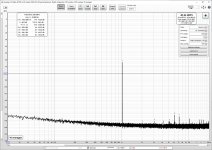
At such low THD levels (<-130db) it is very difficult to obtain consistent results using DIY equipment. Here is a set of measurements to illustrate this inconsistency. The setup in all graphs is the same:
1. Victor LDO balanced output
2. Balanced Twin-T notch (about 64dB)
3. Autoranger mkII
4. M-Audio AP192 soundcard (AK5385 ADC)
The LDO output is set to be same as soundcard FS (4Vrms). In the graphs the Autoranger gain is increased from 0dB to +18dB in 6dB steps. As can be seen the HD levels do not increase consistently with the fundamental. This is probably due to ADC. HD cancellation may also have some impact.
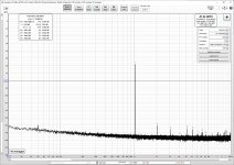
Attachments
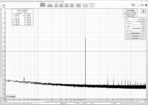
At such low THD levels (<-130db) it is very difficult to obtain consistent results using DIY equipment. Here is a set of measurements to illustrate this inconsistency. The setup in all graphs is the same:
1. Victor LDO balanced output
2. Balanced Twin-T notch (about 64dB)
3. Autoranger mkII
4. M-Audio AP192 soundcard (AK5385 ADC)
The LDO output is set to be same as soundcard FS (4Vrms). In the graphs the Autoranger gain is increased from 0dB to +18dB in 6dB steps. As can be seen the HD levels do not increase consistently with the fundamental. This is probably due to ADC. HD cancellation may also have some impact.
Correct me if I'm wrong - but isn't the purpose of the autoranger to maintain the same output level to the ADC / sound card, regardless of input level to the autoranger?
So for example - if the optimum THD for your ADC / sound card is 1v RMS, then regardless of input level to the autoranger, it should maintain a level of 1v RMS output?
But your plots show varying output levels which is not what I would have expected using the autoranger...
With an AK5572 ADC there is little to worry about once you get below -30dBFS.
EDIT: looks like even -20dBFS is still good enough for < -120dB ADC distortion @ 1kHz. The 5572 is a hell of an ADC...
Assumed a notch depth of 80dB and H2 and H3 at -130dBc, ADC distortion is non-existent. H2 and H3 levels are reported exact to 0.1dB (== no cancelling/addition) and no higher components are seen either. 50dB++ of noise headroom left (assuming we would dig down that deep in the noise floor, not possible of course with a non-synced oscillator). So we could go down to -180dB, theoretically.
This was with the 4493 as DAC (at -30dBFS, where it is good to at least -120dBc on its own) to emulate the notch+LNA output...
Attachments
Last edited:
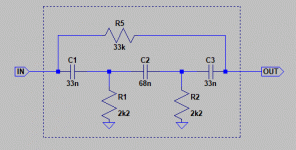
Bad memory here. I opened the notch and now see I've used large metallized polyester (PET) in that one, which are not the best for distortion (and especially not the 63V types).The distortion of the notch is unknown (I'm using WIMA polyprops and off-the-mill metal films).
Simply reversing the notch -- it's symmetric wrt input/output -- changed H3 by more than 5dB to the worse... so this looks like cap distortion contributing to the higher H3 I'm seeing here. The first cap in a Hall notch sees almost the full voltage across itself (80%).
EDIT: Circuit attached.
Attachments
Last edited:
Bad memory here. I opened the notch and now see I've used large metallized polyester (PET) in that one, which are not the best for distortion (and especially not the 63V types).
Simply reversing the notch -- it's symmetric wrt input/output -- changed H3 by more than 5dB to the worse... so this looks like cap distortion contributing to the higher H3 I'm seeing here. The first cap in a Hall notch sees almost the full voltage across itself (80%).
EDIT: Circuit attached.
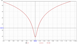
In simulation, that notch filter is -11db at 2kHz with a total notch depth of ~ -43dB (this was with 1% resistors, 5% caps).
So I guess any calculations take the -11dB at the second harmonic into account? As surely you would have to add 11dB to the measured THD not so?
Attachments
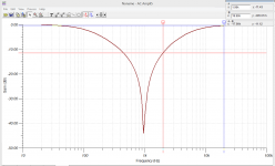
Correct. This is what the "soundcard calibration" with REW affords automatically.In simulation, that notch filter is -11db at 2kHz with a total notch depth of ~ -43dB (this was with 1% resistors, 5% caps).
So I guess any calculations take the -11dB at the second harmonic into account? As surely you would have to add 11dB to the measured THD not so?
Key is *not* to use the "soundcard calibration" feature directly, rather make a normal measurement 0..22050Hz with the notch in place and equal level settings for DAC and ADC (44.1KHz, -3dBFS send level, 512k sequence length, 4 repetitions), export as text, then load it in Preferences-->Calibration. Then remeasure to check if the result is completely flat (you may or may not see a noise wiggle at the notch frequency, depending on depth of the notch).
Attached is measured notch in LoopBack with 10k load-impedance (and 100R source impedance). Because of the high impedance below notch freq, the FR drops significantly from the 10k loading. That's why I designed this notch to be rather low impedance.
Attachments
Thank you Edmond & Steve.
I don't have a problem with increasing the amplitude sensitivity by adding the LNA gain, but IMHO it only goes as far as that, i.e. any clean AC signal presented at the LNA input would appear with the correct level at the ADC input.
But in order to calibrate for distortion I must have either a 5mV signal with a known distortion at the LNA input, or such a signal in the Volt range at the notch filter input. A source like the Victor's, but then it's the one I'm trying to measure because I don't know its distortion.
In other words, are we able to quantify the lowest distortion measurable with a DIY system notch filter/LNA/ADC?
Regards,
Braca
Hi Braca,
It is not generally necessary to know the value of the distortion of the pilot tone as long as it is reasonably small. Lat me give you an example. As I had suggested, if you are trying to measure extremely low values of distortion, set the amplitude of the pilot tone so that it equates to 0.001%, which is -100 dB. You will readily be able to see and measure the value of the pilot tone fundamental to calibrate you system, in situ, at a very low "distortion" level.
Suppose that the pilot tone generator has a rather high 0.1% distortion. That is 60 dB below the pilot tone amplitude, or -160 dB where one or more of its harmonics might show up. Those harmonics, which are readily identifiable by their odd ball frequency, are probably way below what you are trying to measure.
If that is not low enough, it is trivial to find a pilot tone oscillator with 0.01% or less distortion at 1 kHz. I am assuming that you are measuring distortion by looking at an FFT and ignoring the contribution of the line from the pilot tone.
Cheers,
Bob
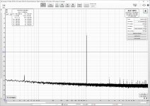
Correct me if I'm wrong - but isn't the purpose of the autoranger to maintain the same output level to the ADC / sound card, regardless of input level to the autoranger?
So for example - if the optimum THD for your ADC / sound card is 1v RMS, then regardless of input level to the autoranger, it should maintain a level of 1v RMS output?
But your plots show varying output levels which is not what I would have expected using the autoranger...
Autoranger also has a variable gain from -42dB to +18dB in 6dB steps. In these examples I used Autoranger as a LNA of 0 to +18dB to illustrate the inconsistencies of THD measurements at low levels. Autoranger has very low THD so it should not have much impact on the measurements.
With an AK5572 ADC there is little to worry about once you get below -30dBFS.
EDIT: looks like even -20dBFS is still good enough for < -120dB ADC distortion @ 1kHz. The 5572 is a hell of an ADC...
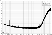
In the measurements I have seen AK5572 suffers from too steep noise shaping so it is not very good for measuring THD at 20kHz. AK5394 was much better in this aspect.
With the noise shaping the THD@20kHz measurement will be limited by the noise. Here is the limit of AK5385.
Attachments
Last edited:
The noise shaping is a bit aggressive for AK5572. That is the trade.
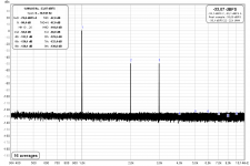
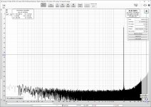
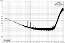
@bohrok2610 - Do you know the real noise floor of your measurement ADC around 1-2-3kHz ? I mean in nV/rtHz.
Here is a measurements of the soundcard input shorted (@48kHz).
Attachments
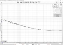
I don't think that's an issue at all.In the measurements I have seen AK5572 suffers from too steep noise shaping so it is not very good for measuring THD at 20kHz. AK5394 was much better in this aspect.
With the noise shaping the THD@20kHz measurement will be limited by the noise. Here is the limit of AK5385.
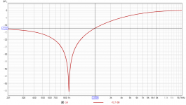
See below plot at 768kHz, mono mode, inputs terminated with 50Ohm (RME ADI-2 Pro FSR, +4dBu ref. level).
At 100kHz we've lost 30dB to the noise floor value at 20kHz.
But with a notch attenuation of, say, 80dB and hitting the ADC with -30dBFS (so same circumstances as I showed in post #9524) we can still go down do -150dBc for a 100kHz component.
The much bigger problem of the AK5572 is the passband ripple in 1x, 2x and 4x modes and the aliasing. It's an audio ADC, clearly not a measurement ADC. Best used at always the highest sample rate and then downsample properly in case it is needed.
EDIT: also added the same measurement in rtHz scale. Noise is contributed by OpAmps and analog front-end in general (and also from the voltage reference), so we can only say the self-noise of the AK5572 is no higher than this (note: Peak Noise is about 8dB higher)
Attachments
Last edited:
1.5 meter
")
So (social) distancing of 1.5m does help to keep it healthy.KSTR, I notice a spur at 8kHz and its harmonics.
It seems that our computers both have the same internal PSU.
In my case they tend to dissapear when the distance between the laptop and the audio interface is more than about 1.5 meters.
- Home
- Design & Build
- Equipment & Tools
- Low-distortion Audio-range Oscillator