I don't think that's an issue at all.
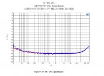
See below plot at 768kHz, mono mode, inputs terminated with 50Ohm (RME ADI-2 Pro FSR, +4dBu ref. level).
At 100kHz we've lost 30dB to the noise floor value at 20kHz.
But with a notch attenuation of, say, 80dB and hitting the ADC with -30dBFS (so same circumstances as I showed in post #9524) we can still go down do -150dBc for a 100kHz component.
Ok. That looks good and much better than the AK5572 evaluation board (below).
Attachments
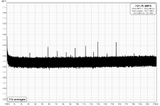
KSTR, I notice a spur at 8kHz and its harmonics.
Correct, but look at the orders of magnitude! That little 8kHz spikey is more than 40dB below the 20Hz..20kHz rms noise floor (and some 20dB below 24bit resolution, mind you, only captured by the self-dithering from the random noise). It's not even visible in a 4M FFT without averaging.8kHz is USB2 microframe frequency. Perhaps that being the culprit?
Note also that at 768Khz the packet size is large, increasing packet noise. At 44.1Khz there is not even a hint of it even when maxing out all possible resolution (there are some other "birdies" now, equally utterly irrelevant).
The interface is hooked up as isolated and floating as it ever gets, practically. USB feed is via Intona USB2 Isolator which reduces 8kHz packet noise and does full galvanic isolation, and the supply of the RME is ultra low-leakage medical DC/DC. I actually do "hot wire" measurement with this setup.
Attachments
We don't know the measurement conditions (FFT size, notably), so no way to really compare.Ok. That looks good and much better than the AK5572 evaluation board (below).
Never thought to see the hot wire technique mentioned in an audio forum.KSTR said:I actually do "hot wire" measurement with this setup.
I used it way back for turbulence measurements in an air flow boundary layer. However, there were no ADCs at that time.
Hi Bob,Bob Cordell said:Hi Braca,
It is not generally necessary to know the value of the distortion of the pilot tone as long as it is reasonably small. Lat me give you an example. As I had suggested, if you are trying to measure extremely low values of distortion, set the amplitude of the pilot tone so that it equates to 0.001%, which is -100 dB. You will readily be able to see and measure the value of the pilot tone fundamental to calibrate you system, in situ, at a very low "distortion" level.
Suppose that the pilot tone generator has a rather high 0.1% distortion. That is 60 dB below the pilot tone amplitude, or -160 dB where one or more of its harmonics might show up. Those harmonics, which are readily identifiable by their odd ball frequency, are probably way below what you are trying to measure.
If that is not low enough, it is trivial to find a pilot tone oscillator with 0.01% or less distortion at 1 kHz. I am assuming that you are measuring distortion by looking at an FFT and ignoring the contribution of the line from the pilot tone.
Cheers,
Bob
Thank you for the detailed explanation.
I've been aware of the method ever since I assembled your Distortion Magnifier, but never thought about it in the context of the notch filter measurement. It certainly makes sense knowing that a linear system will preserve the harmonics' profile as the signal level is reduced.
I've got a couple of oscillators laying around, the distortion profile of which can be tweaked, so I'll only need to build an attenuator.
However, since the notch filter input is at the same time the input of my measurement chain, I can currently use the pilot tone for the calibration only. Mixing it with a DUT's signal would probably call for an active summing circuit.
Regards,
Braca
We don't know the measurement conditions (FFT size, notably), so no way to really compare.
True. We also don't know the FFT size in your graph. What was it?
Ooops, misunderstanding here. "Hot wire" was meant to refer to low-level measurements within a high potential environment, like mains or inside tube amps.Never thought to see the hot wire technique mentioned in an audio forum.
I used it way back for turbulence measurements in an air flow boundary layer. However, there were no ADCs at that time.
4M.True. We also don't know the FFT size in your graph. What was it?
Btw, REW takes FFT gain into account when selecting rtHz Y-axis scale so once you set the 0dBFS value correctly for the input, noise measurement is correct regardless of FFT size (+- a few dB).
Last edited:
No problem.
To me, "hot wire" means "hot wire anemometry". No wonder - my basic training is Mech. Eng.
To me, "hot wire" means "hot wire anemometry". No wonder - my basic training is Mech. Eng.
Below 10nV/rtHz is a remarkable noise floor. RME ADI-2 Pro is certainly a very good performer. Just a bit pricey...
EDIT: also added the same measurement in rtHz scale. Noise is contributed by OpAmps and analog front-end in general (and also from the voltage reference), so we can only say the self-noise of the AK5572 is no higher than this (note: Peak Noise is about 8dB higher)

Hi Bob,
Thank you for the detailed explanation.
I've been aware of the method ever since I assembled your Distortion Magnifier, but never thought about it in the context of the notch filter measurement. It certainly makes sense knowing that a linear system will preserve the harmonics' profile as the signal level is reduced.
I've got a couple of oscillators laying around, the distortion profile of which can be tweaked, so I'll only need to build an attenuator.
However, since the notch filter input is at the same time the input of my measurement chain, I can currently use the pilot tone for the calibration only. Mixing it with a DUT's signal would probably call for an active summing circuit.
Regards,
Braca
Hi Braca,
No need for an active summing circuit. Just inject a tiny current from the pilot oscillator into the output lead of the oscillator you are testing. For example, if you are testing a Victor oscillator with 100-ohm output impedance and you connect the test oscillator to it through a 1M resistor, you will have a 10,000:1 attenuator. If Victor's oscillator was operating at 1V and your pilot oscillator were operating at 1V, then you would see the pilot tone on the spectrum analyzer down 80 dB from the Victor oscillator fundamental, and see effectively 0.01% "distortion". If you set the pilot oscillator to 100 mV, you will see the pilot tone marker at a level of 0.001%. You can verify the above by using a signal chain that has no notch filter at first.
In my setup, I built a frequency-compensated passive twin-T filter with an associated LNA. A special filter after the twin T makes the twin T response pretty flat at the 2nd harmonic on up, and actually enhances the effective notch depth.
This is the case because the first stage of the compensation filter is a second-order state variable HPF tuned to the vicinity of the 2nd harmonic frequency with high enough Q to provide peaking that compensates for the passive twin T's loss at the second harmonic. As a result of its being an HPF at 2 kHz, it actually adds further loss at the 1 kHz fundamental frequency.
A second state variable filter is used as part of an arrangement to further flatten the distortion frequency response. Its action is primarily to make the distortion frequency response at the 2nd and 3rd harmonics the same.
The use of the accurately compensated twin T filter greatly simplifies measurements because I no longer have to worry about taking into account the attenuation of the passive twin T filter at the 2nd, 3rd, etc harmonic frequencies. It also helps to avoid cockpit errors.
I then take the output of the LNA and feed it into my THD analyzer set to 1 kHz. There is a further trick I use to provide the analyzer a fundamental signal with enough amplitude for the THD analyzer to properly auto-tune.
I then take the residual output of the THD analyzer and send it for FFT analysis to my QA401. I use a very large FFT with many averages to get the noise floor down below the distortion lines.
Cheers,
Bob
I'll try to demonstrate this pilot tone method later tonight. With the Viktors, it very easy to add the injection to the output as it's a dual mono wired 2xRCA output. Just need to cut the trace to one RCA and insert the 1Meg there, and feed it from the aux oscillator (soundcard output).No need for an active summing circuit. Just inject a tiny current from the pilot oscillator into the output lead of the oscillator you are testing. For example, if you are testing a Victor oscillator with 100-ohm output impedance and you connect the test oscillator to it through a 1M resistor, you will have a 10,000:1 attenuator. If Victor's oscillator was operating at 1V and your pilot oscillator were operating at 1V, then you would see the pilot tone on the spectrum analyzer down 80 dB from the Victor oscillator fundamental, and see effectively 0.01% "distortion".
Here we go....
I wasted half an hour or so because the pilot level was way off at first (too high, also varying a bit with frequency, wtf?) but after looking closer on the board I saw it has 600Ohms output impedance (correct to the schematic that I should have checked first, meh), so I had to reduce the pilot send level accordingly. It also means the notch correction is off at higher frequencies, for the harmonic levels and the 5.5kHz pilot (by ~1.5dB).
Test level was 1Vrms, at this level this first generation Viktors still does pretty well. At 1V the notch distortion will be somewhat lower, too. Still enough uncertainity here, of course.
Looking at the osc with a faster real-time FFT (32k) showed a lot of fluctuation of H2 level and general noise floor jumping up and down (LM4562 popcorning)
Attachments

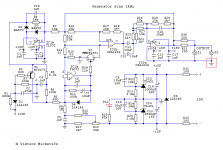
New revision of the oscillator board has been made. Now the AGC fet is connected to the non inverted input of the opamp. This configuration is less sensitive to interference, less parasitic capacitance at the inverted input of the opamp and also the signal over the fet can be two times lower due to the non inverted gain of the opamp.
Vic.
The RCA connector is still connected to GND right?
Regards,
TJ.
Attachments
Hi Bob,Bob Cordell said:Hi Braca,
No need for an active summing circuit. Just inject a tiny current from the pilot oscillator into the output lead of the oscillator you are testing. For example, if you are testing a Victor oscillator with 100-ohm output impedance and you connect the test oscillator to it through a 1M resistor, you will have a 10,000:1 attenuator. If Victor's oscillator was operating at 1V and your pilot oscillator were operating at 1V, then you would see the pilot tone on the spectrum analyzer down 80 dB from the Victor oscillator fundamental, and see effectively 0.01% "distortion". If you set the pilot oscillator to 100 mV, you will see the pilot tone marker at a level of 0.001%. You can verify the above by using a signal chain that has no notch filter at first.
Cheers,
Bob
Thank you very much.
After this explanation, applying a pilot tone is certainly much easier than I thought, and I will definitely give it a try.
Regrads,
Braca
It certainly seems so. I've known of an issue with 1kHz in connection with USB2 and have seen it with another laptop.8kHz is USB2 microframe frequency. Perhaps that being the culprit?
Thank you for a useful information.
Regards,
Braca
Actually the 1kHz issue (even USB2 highspeed audio devices often send isochronous packets only every 1ms - bInterval=4) makes me wonder why so many people using USB audio gear take their measurements at exactly 1kHz, to have their results possibly skewed by the USB spuriae.
With RME this is a non-issue. With other interfaces, less so, notably when they are not asynchronous isochronous (== not clock master), stuff like the old USB 1.0 PCM2702, or bus-powered devices (supply modulation).
In modern DACs packet noise most often is a layout issue (polluted GND)
EDIT:and even more often it's a cabling error in the test setup (unbalanced, "ground loop"), increasing the error at the receiving end (the analyzer) even when the analog output right at the DAC outputs itself is clean.
In modern DACs packet noise most often is a layout issue (polluted GND)
EDIT:and even more often it's a cabling error in the test setup (unbalanced, "ground loop"), increasing the error at the receiving end (the analyzer) even when the analog output right at the DAC outputs itself is clean.
Last edited:
Actually the 1kHz issue (even USB2 highspeed audio devices often send isochronous packets only every 1ms - bInterval=4) makes me wonder why so many people using USB audio gear take their measurements at exactly 1kHz, to have their results possibly skewed by the USB spuriae.
That's why you often see people use 997 Hz as the fundamental.
Jan
- Home
- Design & Build
- Equipment & Tools
- Low-distortion Audio-range Oscillator