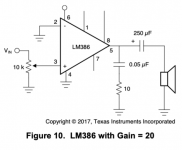
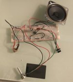
I followed Fahey's advice and breadboarded the most basic illustration in the LM386 datasheet, Figure 10, "LM386 with Gain = 20." It took about 15 mins, including searching for parts. A 12V wall wart is used for power.
I had this post open and typed additional info as I tried various things.
I have sound. Up to about wiper position 2-3, I hear notes and no hum or buzz from the cheapo speaker. However, when I turn the volume pot up, a lot of noise and hum is added to the speaker output. That is with both guitar gain knobs at 0 and the stompbox gain setting as low as it goes. The noise appears almost immediately when I turn up gain on the guitar or stomp box.
Right now, I suspect this problem is due to the input source being a guitar (electric) going thru a stomp box powered by a 9V wall wart.
When I put a 0.1uF, 1uF, and then 10uF cap (one at a time) in series between the middle 10k pot prong and pin 3, no difference. With any of those caps in place and the volume pot at 0/10, I hear a short noise when I plug the wall wart into the DC jack. When I eliminate the cap in series and instead run a line "off the side" of the going-to-pin3 wire with a 10uF cap and 10ohm resistor to ground, that noise of plugging the wall wart into the DC jack is constant, even when the volume pot is at 0/10.
Just now, after eliminating the cap & resistor, the noise was constant after plugging the wall wart into the DC jack, even with the volume pot at 0/10 and the stomp box powered off.
With the guitar plug removed from the jack and the volume pot at 0/10, the noise is now constant after I plug the wall wart into the DC jack. When I touched the pot several times just now, the noise would go away while my fingers were in contact, come back when I removed my fingers, and after the 3rd or 4th time the noise did not return after I removed my fingers.
I just noticed that notes and noise are coming from the speaker even when the volume pot is at 0/10. Turning it up to 10/10 does not silence the notes or noise. The +/tip prong of the 2-prong guitar jack is connected to the left pot lug (viewed from rear), the center prong is connected to pin 3, and the right prong goes to ground. I removed and reinserted the wall wart and this time I hear noise only when the volume pot is > 0/10. A little later, the noise is constant again even when the volume pot is 0/10.
When I tried swapping the wires connected to pot lugs 2 and 3, no difference - same constant noise when wall wart is plugged.
This is driving me nuts. I am getting inconsistent results with the same setups, sometimes changing when I touch the volume pot. My guess is some kind of short or grounding problem, but I have followed Figure 10 exactly - with the exception of changes made to see if they make a difference, e.g. the experiments between the pot and pin 3, since eliminated.
Last edited:
Yup, no surprise. The coupling cap's job is to pass the guitar signal on to the LM386; it won't remove hum.When I put a 0.1uF, 1uF, and then 10uF cap (one at a time) in series between the middle 10k pot prong and pin 3, no difference.
Without a schematic showing your changes, I have no idea what "off the side" means.When I eliminate the cap in series and instead run a line "off the side" of the going-to-pin3 wire with a 10uF cap and 10ohm resistor to ground, that noise of plugging the wall wart into the DC jack is constant, even when the volume pot is at 0/10.
More importantly: what was your reasoning for all this mucking about with caps? What electronics principles are you using? Why do you expect that adding capacitors here and there will change the level of hum you're hearing?
Perhaps I'm wrong, but it appears as though you're making random changes, hoping something will work. I have never known this approach to work in electronics. Circuits behave according to pretty well-defined physical and mathematical principles, and you have to understand those principles in order to make changes that lead anywhere.
I an think of two hypothesis to explain all these intermittent problems you're experiencing:When I touched the pot several times just now, the noise would go away while my fingers were in contact, come back when I removed my fingers, and after the 3rd or 4th time the noise did not return after I removed my fingers.
1) You have loose connections. This is quite common with a solderless breadboard, particularly if it's not a new one, and the internal spring clips have lost their tension.
2) Your chip amp is oscillating like crazy at a frequency too high to hear, and when you touch part of the circuit, the oscillation momentarily stops or changes.
Then it's still wired incorrectly (or there is no ground connection.) Did you follow the picture I posted for you in post #31, and updated for additional clarity in post #47?I just noticed that notes and noise are coming from the speaker even when the volume pot is at 0/10.
10/10 is maximum volume. That certainly won't silence the amp.Turning it up to 10/10 does not silence the notes or noise.
This does not tell me what you've done. Are the pot lugs pointing down, or up? "Left" changes depending on which way the lugs point!The +/tip prong of the 2-prong guitar jack is connected to the left pot lug (viewed from rear)
Refer to the diagram, attached once more to this post. I can't think of any way to make it any simpler than that.
Once again, what was the reasoning behind this wire swapping? Was it just random? Making random changes is almost never going to be helpful in solving a problem like this.When I tried swapping the wires connected to pot lugs 2 and 3, no difference - same constant noise when wall wart is plugged.
Really sounds like an oscillating chip to me, but I'm guessing from far away.This is driving me nuts. I am getting inconsistent results with the same setups, sometimes changing when I touch the volume pot.
Is there anybody local you can reach out to for help? Is there a hackerspace in your area? Perhaps a community college with an electronics program, where someone might give you a few minutes help? Any ham radio operators or clubs around?
-Gnobuddy
Attachments
My starting point is the attached schematic from the datasheet.
My thinking with the caps was that the hum/noise might be due to DC on the signal from the jack. The idea of using them in series was to try to filter out any such DC where it might not belong. The path "off the side" from the pot to pin 3 was from that line to ground, with the cap and resistor in between, by analogy to both decoupling the + and - from a PSU and the cap & resistor from pin 5 to ground before the speaker cap. I anticipated that someone might suggest doing one or both of these so I just tried it to save time. I learned that both changes in this area of the schematic do not help.
I moved everything - the attached schematic with no changes - to a new, virgin breadboard. No sound whatsoever. With both guitar (and stomp box) and iPhone as audio sources. I have very carefully double-, triple-, and quadruple-checked and it's all as shown on the attached schematic. Dead silence from the speaker.
I wired the pot exactly as shown on your diagram. I have checked and re-checked multiple times. I tried swapping the 2 leads just in case I had them backwards, or just in case the pot may be non-standard. The ground lug goes to ground; I have checked and rechecked that multiple times.
I tried both 0/10 and 10/10, and in-between, just in case I had somehow miswired or inverted clockwise and counter-clockwise pot functioning. I also tried removing the pot and connecting the audio jack data line directly to pin 3; no difference.
I have a bunch of these chips and have tried several; no difference.
I have no way to test for, and wouldn't have a clue how to fix, a chip oscillating wildly or otherwise.
I have a friend who is an engineer at JPL. He has commented that he was where I am 60 years ago. I'll ask him to take a look.
BION, I'm not an idiot, although I sure feel like one now.
P.S. The 12VDC wall wart that I am using has only 2 prongs and not a grounding prong. By analogy to the main panel on the side of my house, where neutral and ground wires all attach to the same buses (2 x 120 buses), I have treated the - as ground and/or connected it to ground. The DC jack has 3 lugs, center +. I have treated as - the lug that allows me to take a multimeter reading (along with +) and as ground the lug that does not produce a DMM reading (along with +). I have tried connecting both the - and ground lugs to ground, and I have tried connecting only the - lug to ground; no difference. Should I try running a wire from the ground prong hole in a wall receptacle directly to the - rail of my breadboard?
Attachments
Last edited:
I hope that is more figurative than literal. 🙁I give up.
Worth noting: decades ago, the US military used to test incoming candidates for possible training as electronic technicians. I was told by a former colleague (who had been in the military in the '60s and '70s) that only about one in five of those tested showed any aptitude at all for electronics. It isn't for everybody - and that's no reflection on those whose brains aren't wired to like it, or to be good at it.
Clearly, you and the LM386 do not get along. So, if you still have any interest in pursuing electronics, I suggest you take a couple of steps back, and start over with something much simpler (and much less finicky) than a chip-amp.
Once you can build that very simple circuit a dozen times in succession, and have it work every time, with no mysterious problems surfacing every ten minutes, you know you're ready to move on to the next step. 🙂
Step 1: Use my image as a guide. Plug your two speaker wires into two different power rails of the breadboard. (If you don't know how the breadboard works internally, read this: How to Use a Breadboard )
Step 2: Add the filter capacitor, wired across the two power rails (you'll need to add additional wire, the cap leads won't be long enough.)
The filter cap is not necessary for this circuit, but it should become force of habit to ALWAYS use a filter cap across the power supply rails with every audio circuit you build. You can leave the cap in place as you start to make this circuit more complex over the next few days.
Step 3: Plug the (-) battery wire into the (-) power rail of the board as shown.
Step 4: Plug a short length of wire into the (+) power rail of the board as shown. You should get a "click" when you touch the two wire ends together. You do? Success!
Step 5: Draw a schematic diagram of the circuit that you've just constructed. Until you can read and draw schematic diagrams, you will never grasp what's going on in a circuit...so it's time to start right now. Pictures won't do the trick.
This is pretty much the simplest circuit that exists...one resistor (loudspeaker), one battery, two wires connecting them.
Get this working, and the next step will be to add a single transistor that will become a simple amplifier. Transistors are cheap, and less fussy than an LM386.
-Gnobuddy
Attachments
I hope that is more figurative than literal. 🙁
...
Clearly, you and the LM386 do not get along. So, if you still have any interest in pursuing electronics, I suggest you take a couple of steps back, and start over with something much simpler (and much less finicky) than a chip-amp.
Yes, only figurative. It lasted long enough to get a cup of coffee.
The NTE823 is supposed to be the same as the LM386, but maybe it's not exactly the same. The datasheet is very limited and does not include any exemplar schematics. I just ordered the real deal from Radio Shack and will pop it in on receipt. In the meantime, I will see if I can handle your simple circuit.
Attachments
Last edited:
Get this working, and the next step will be to add a single transistor that will become a simple amplifier. Transistors are cheap, and less fussy than an LM386.
It's alive!
I don't have any transistors. What should I get for this purpose?
For background: when a person is trying to learn how to write his/her first computer program, it has become tradition to write a program called "Hello, world", which does only one thing: it prints out the message "Hello, world!", and stops.In the meantime, I will see if I can handle your simple circuit.
In any sane programming language, this will be a very short, very simple program. So why is this invariably the first program a novice writes?
The simplicity of the code is the whole point: to get even the simplest program to work, there is a lot of background stuff that the programmer has to sort out first. She needs to find a suitable editor (or programming environment. She has to get every last minute part of the program right - leave off one semi-colon or one curly brace ({) and the program won't work. She may have to install a compiler, and find out how to run it. She may have to link pre-existing libraries to the bit of programming code she wrote (for example, in the C and C++ languages, you need to include a specific library before you can print out anything.)
So the "Hello world" program is designed to get the programmer familiar with all this mundane background stuff, while the program itself is so simple that it is hard to screw it up too badly. Having mastered all this background stuff, the programmer can then focus on writing more complicated (and therefore, more failure-prone) programs, without going crazy trying to figure out whether the problem is in the code she wrote, or because one of the other half a dozen things isn't being done correctly.
The "make the speaker click" circuit is my equivalent of the "Hello, world!" computer program. The circuit itself is ridiculously simple. But to make it work, you have to understand how the breadboard works, solder successfully to the speaker lugs and battery leads, figure out which end of an electrolytic capacitor is positive and what its capacitance and voltage rating are, find a good battery (and learn how to recognize a bad one), learn how to strip wire ends, obtain wire of the proper gauge (22 gauge is perfect for breadboards), obtain wire of the proper type (solid-core, not stranded, and get several different colours), and so on.
The point of building the "speaker click" circuit is to get all this other stuff under your belt. Hopefully that will later translate to fewer mysterious and blood-pressure-raising problems when you build your next, slightly more complicated, circuit.
The final step I suggested in the "speaker click" circuit - translating from breadboard layout to schematic diagram, or vice versa - is really important. Without that, a person can only operate in "monkey see, monkey do" mode, which is intellectually unsatisfying, and likely to result in circuits that don't work.
-Gnobuddy
The final step I suggested in the "speaker click" circuit - translating from breadboard layout to schematic diagram, or vice versa - is really important.
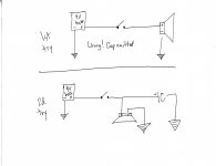
My first attempt was wrong because I omitted the cap. The second schematic includes the cap; this is the kind of config I would describe as "hanging off the side" of the line.
One thing I don't know is whether the circuit would be essentially the same if the physical location of the speaker and the cap were swapped, such that the cap would "hang off the side" (i.e. go to ground) before the speaker.
It seems that the cap to ground after the speaker "bleeds" something to ground and, in so doing, affects the energy available to the speaker. However, I have no idea (a) what is bled off to ground or (b) how the energy available to the speaker is different from what it would be available if the cap were eliminated.
There's no voltage division because there are not 2 resistors before (or at all) the speaker.
I'm inclined to think that DC is not removed from the energy reaching the speaker because the cap is after the speaker. Also, I don't think we would want to - or even can - remove DC because there is no separate signal in this circuit, and because the speaker needs DC.
I can't for the life of me see any useful purpose fulfilled by the cap.
Attachments
Last edited:
Great! (I wrote my previous post before I read this one of yours, so it may be a bit out of sequence. 🙂 )It's alive!
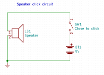
Did you draw the schematic of the "speaker click" circuit? Simply follow each wire in turn, noting what's connected to each end. Draw it out; from the battery, where does the (-) terminal connect to? Where does the (+) terminal? And so on.
You should end up with something like the first of the two attached images below.
Any small-signal, silicon, NPN transistor. If you're fortunate enough to have a local electronics store, they may carry the ancient (but perfectly usable) 2N2222. Or your EE friend might have something suitable in the parts-bin.I don't have any transistors. What should I get for this purpose?
There are plenty of other possible transistors - what you're looking for is a small-signal NPN transistor with wire leads slim enough to poke into a breadboard. (Bigger transistors will have leads too fat to poke into a breadboard without damaging the metal clips inside.)
For now, let's say you got yourself a few 2N2222s. You'll also need a 100k resistor (learn the resistor colour code while you're at it - how do you know that it's really 100k? What does the "k" mean? What is the unit of resistance?)
For the next step after this one, you'll also need a small electrolytic capacitor; something like 10uF, rated for at least 12 volts. (I think you already have something suitable, based on your previous posts.)
Having obtained your transistor(s), the next step is to Google for the datasheet. For instance, if you get some 2N2222s, Google the term "2N2222 datasheet".
Once you have the datasheet, use it to identify the three leads of the transistor. One will be called the emitter, one the base, and the last, the collector. The datasheet will have a drawing of the transistor case (which invariably has a flat side or other asymmetry so you can identify it's orientation), and the drawing will indicate which lead is which. Often the leads will be numbered (1, 2, 3), and nearby there will be text that reads something like "1 - emitter, 2 - base, 3 - collector".
Once you've figured out which lead is which, you have one more thing to figure out. Somewhere in the datasheet there will be a line (or several lines) specifying the DC current gain of the transistor. For the 2N2222, there are a number of lines, but the nutshell version is that the current gain will be somewhere between 100 and 300 for our purposes.
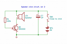
Once you've got all this figured out, build the circuit in the second image I'm attaching, on your breadboard. This time it's up to you to figure out where to place the transistor, and how to connect the wires to create the schematic I've shown. (How can you tell which transistor lead is the emitter in the schematic, which the base, which the collector? If you don't know, Google is your friend.)
This circuit, built correctly, will do exactly the same thing as the first one - it will produce a click from the speaker when powered on.
But - our transistor is one small step away from greatness now. All will be revealed once you've got this step under your belt, and have successfully built it and got it working. 🙂
By the way - tomorrow is going to be a very busy day for me at work, so I might not find time to post here until the day after. I'll try, but there is a chance I won't be able to.
-Gnobuddy
Attachments
Excellent! You did your homework! That makes me happy. 🙂The second schematic includes the cap; this is the kind of config I would describe as "hanging off the side" of the line.
There is simply no good way to describe a schematic to someone else in words, which is why we use schematic diagrams for the purpose!
However, feel free to describe it to yourself in whatever way makes sense to you - always keeping in mind that the same words probably won't make sense to anybody else! 🙂
There are some rules-of-thumb which we can use to make a circuit more readable. For one, we use symbols (rather than pictures) for everything. You can see I've used a symbol for the battery in the schematics I've attached to this post, rather than draw a picture. It actually makes it easier to read, in the same way that a word in English can convey much more than a pictogram (imagine a pictogram that depicts the same thing as the word "frustratingly"? It can't be done, which is why too many emojis makes for infantile and limiting writing.
Another good convention is that we draw wires as straight lines, either vertical, horizontal, or at 45 degrees to the vertical. (You've already done this, good!)
One convention I try to use when possible is to place the power source (battery or power supply) on the right end of my schematic.
Another convention I use almost always is to draw negative voltages near the bottom edge of my schematic, and positive voltages near the top edge.
You can see that these last two guidelines dictated how I oriented and placed the battery symbol in the two diagrams I attached to my previous post.
Good question, and the answer is, yes, the circuit would be the same. For our understanding at this stage of the game, every point connected to the same wire is electrically joined together. There is no difference, electrically, between the "left" or "right" end of the wire.One thing I don't know is whether the circuit would be essentially the same if the physical location of the speaker and the cap were swapped, such that the cap would "hang off the side" (i.e. go to ground) before the speaker.
If you ever get to radio frequency circuits, this simplification has to be re-thought, and we have to start worrying about the two ends of a wire not being exactly the same thing. But for now, for this very simple speaker click circuit, every point on the same wire is electrically identical, and you can swap them at will, particularly in order to make schematic diagrams clearer and easier to read.
Until you learn more about capacitors, I'll give you an analogy. Imagine the battery is an air compressor; it pushes out electric "pressure" (voltage), where the compressor pushes out air under pressure.It seems that the cap to ground after the speaker "bleeds" something to ground...
Every air compressor includes an air-tank, a reservoir for compressed air. This smooths out fluctuations in the flow of air from the compressor, so we have a steady high pressure.
The capacitor you've wired across the battery does the same thing for electricity. It is a reservoir for electrons; it smooths out any fluctuations in the voltage from the battery (or power supply, when that's used instead.)
Correct! We're applying the full battery voltage to the speaker in this case.There's no voltage division because there are not 2 resistors before (or at all) the speaker.
This will change - look at the second image I've attached. The transistor behaves as a resistor of sorts, and it is in series with the loudspeaker - ta da, a voltage divider, and a special kind of one, as we'll see later!
For the first speaker-click circuit, it serves no purpose other than to remind you to ALWAYS include such a filter cap in every single audio circuit you ever build. 🙂I can't for the life of me see any useful purpose fulfilled by the cap.
Hang on, that cap will serve a very useful purpose in the next iteration of the circuit. I promise!
-Gnobuddy
I bought Platte's Make: Electronics book. I'm placing an order today for the key parts needed for most of his experiments (the Arduino stuff can wait), including some 2N2222s. (He does not get to the LM386 until almost page 300, toward the end of the book.)
No worries re getting busy. You have already gone way, way above and beyond; very much appreciated. Besides, I will need to wait for the parts to arrive. In the meantime, I will dig into the Anderton book.
No worries re getting busy. You have already gone way, way above and beyond; very much appreciated. Besides, I will need to wait for the parts to arrive. In the meantime, I will dig into the Anderton book.
For our understanding at this stage of the game, every point connected to the same wire is electrically joined together. There is no difference, electrically, between the "left" or "right" end of the wire.
If you ever get to radio frequency circuits, this simplification has to be re-thought, and we have to start worrying about the two ends of a wire not being exactly the same thing. But for now, for this very simple speaker click circuit, every point on the same wire is electrically identical, and you can swap them at will, particularly in order to make schematic diagrams clearer and easier to read.
I need to keep reminding myself of that.
I was reminded of another wonderful free resource: Textbook for Electrical Engineering & ElectronicsI need to keep reminding myself of that.
These are a series of six textbooks, and between them, they cover a lot of ground. They are real textbooks, of the sort that might be used in a high-school or junior college program. This is the sort of thing you take your time wading through, as there will be lots to learn along the way.
These might be a nice complement to the quick-and-easy electronics project book you just bought.
-Gnobuddy
Still waiting for parts to be delivered....
That looks like a great resource. Thank you. My JPL friend also recommended The Art of Electronics 3rd Edition | by Horowitz and Hill .
That looks like a great resource. Thank you. My JPL friend also recommended The Art of Electronics 3rd Edition | by Horowitz and Hill .
A wonderful choice - that book has been one of the gold standards for university-level electronics students for decades. I have an ancient version that I had to save up for months to buy. It's traveled to three different countries with me, passing through a couple more on the way. It's a keeper!My JPL friend also recommended The Art of Electronics 3rd Edition | by Horowitz and Hill .
Horowitz and Hill is a fairly advanced book, and a thick one at that. I've never used it as an introductory textbook myself - my students were not that capable.
My suggestion would be, try to get a peek at the book in a bookstore (or via an online preview PDF) before you decide to buy it.
-Gnobuddy
Is there a Fry's Electronics in your area? There were three within driving range when I lived in Los Angeles, and that was a boon when I didn't want to wait a week for mail-ordered parts to arrive. I lived not too far from JPL, in L.A. near the city border with South Pasadena.Still waiting for parts to be delivered...
Mail-ordering parts is particularly annoying when you realize you're missing a couple of fifty-cent parts, and are going to have to spend another five bucks on shipping, and wait another week for delivery, to get them!
Have you discovered All Electronics yet? All Electronics is one of the last survivors of what used to be a wide variety of electronics surplus stores in the general vicinity of L.A. Almost all the others have given up and shut down over the years. Here's their website: All Electronics | Electronic and Electro-Mechanical Parts and Supplies at Discount Prices .
If you like tinkering with electronics and electro-mechanical things, the place is well worth a visit. They also do mail-order, if you don't want to take a long drive out to the 'valley.
Obligatory warning: All Electronics can be dangerous to the fatness of your wallet, and the health of your bank account. 😱
-Gnobuddy
Ugh! I lost a reply when I checked a prior page.
In short, I received the LM386 order but won't receive the big one (almost everything for Platte's book). Replacing the NTE823 with the LM386 gave me noisy sound again, less when I replace the 12V wall wart with a 9V battery, and more when I turn on the stomp box (powered by a separate 9V wall wart). I hesitate to try all the same enhancements again because that feels like the definition of insanity, but it's the only way to know for sure whether a key cause of my problems has been that the NTE823 may not be an exact substitute for the LM386. ... Later.
I have a headache. Time for shopping therapy. While waiting for my big order - coming from South Carolina and, not as I expected, from Arizona - should I pick up any more parts, in addition to the transistor you mention above?
Last edited:
Have you discovered All Electronics yet?
Just went to All Electronics for the first time. Great store!
Fry's around here is not what it used to be, probably due to online competition. Vast sections are poorly stocked. Hardly any staff or customers. The sense I get as I walk around is that they can't stay in business like this. It's too bad because they used to be great stores.
I had a lot of trouble adding the 2N2222A. It helped to find a datasheet from a different manufacturer. I was discombobulated by turning the transistor right side up after reviewing the layout showing the transistor upside down.
The gain numbers are listed under Electrical Characteristics and vary with test conditions. The lowest min is 30 and the highest max is 325.
On your second schematic, 1 (emitter) goes to ground. 2 (base) is connected to one end of the resister; the other end of the resistor is connected to line 1 (+) originating from the battery. 3 (collector) is connected to the neg (-) line out of the speaker; this required that I disconnect the neg (-) speaker wire from ground and connect it instead to the collector. I hear sound but I cannot say it's louder to my 59YO ears.
I really have no idea what, if anything at this point, the transistor and resister are doing, or what it accomplishes to run the neg (-) speaker wire thru the transistor rather than directly to ground.
Last edited:
- Home
- Live Sound
- Instruments and Amps
- Why does this LM386 breadboard not work as a guitar amp?