It will be easier next time; this is exactly the sort of thing I meant when I said that there is a lot of background stuff you have to get familiar with, even to build a very simple circuit.I had a lot of trouble adding the 2N2222A.
IMO, solderless breadboards are both good and bad. They're good because it's so easy to plug a component in, or remove it. They're bad because their rigid layout of holes and tracks forces you to place components and wires in a way that usually makes it hard to "see" the schematic from the physical parts layout, and tends to create a rat's nest of wires.
I understand. I remember going through this same thing myself. And it got worse when I first started to use integrated circuits - because those cost more money than a single transistor, and if I got the pins wrong, there was a good chance of frying the IC as soon as I applied power. And I was just a kid with no money, so if I fried an IC, I would have to wait a month for my few bucks of pocket-money to buy a replacement. Torture!I was discombobulated by turning the transistor right side up after reviewing the layout showing the transistor upside down.
Yes! And this is another important thing to notice. Semiconductor devices have terrible manufacturing tolerances when it comes to their electrical parameters. In this case, the current gain of the 2N2222 varies randomly over 11:1 range! Imagine if a 1" bolt could actually be anywhere between 1" and 11" long? 🙂...gain...vary with test conditions...min is 30 and the highest max is 325.
All of that sounds good. 🙂On your second schematic, 1 (emitter) goes to ground. 2 (base) is connected to one end of the resister; the other end of the resistor is connected to line 1 (+) originating from the battery. 3 (collector) is connected to the neg (-) line out of the speaker; this required that I disconnect the neg (-) speaker wire from ground and connect it instead to the collector.
It might actually be a little quieter than the original (no-transistor) circuit, but there's a good reason for that, as you'll see in a minute!I hear sound but I cannot say it's louder to my 59YO ears.
Okay. I think we're ready to talk about that now. This is the good stuff you've been building up to learning!I really have no idea what, if anything at this point, the transistor and resister are doing, or what it accomplishes to run the neg (-) speaker wire thru the transistor rather than directly to ground.
Firstly: An audio signal (voltage) is an electrical voltage that varies with time, in a way that is a copy of the varying sound pressure that we turned into the audio signal. I mean, if you play a note on a piano, the air near the piano vibrates in a very specific way, and by placing a microphone there, the microphone generates an electrical voltage that varies in the same way the air pressure did near the piano - it's a copy of the original sound, but in electrical form.
Secondly: if we send this varying electrical voltage into a loudspeaker, we will get an (imperfect) reproduction of the original sound back. This was Alexander Graham Bell's enormous contribution to humanity - the telephone.
However, the sound coming out of a telephone like this is very, very quiet; much quieter than the original piano note, so quiet that we had to press the telephone against our ear to hear anything.
Thirdly: at first with vacuum tubes, later with transistors and their kin, we learned how to "amplify" the weak electrical signal, meaning make it stronger, without changing its shape (much).
Sending the stronger signal into a telephone "speaker" made the speaker louder. Sending an even stronger signal into a loudspeaker makes it, well, speak loudly. 🙂
But how does a vacuum tube, or transistor, actually do this? How do you take a weak, time-varying current, and make it bigger, while distorting it as little as possible in the process?
The simplified answer is that our tube or transistor can be made to behave like a variable resistor. But a special kind of variable resistor: instead of turning a shaft with our fingers to change its resistance, we can change its resistance by applying a tiny varying voltage to one of its electrodes - the base, in the case of the transistor.
This has enormous consequences: we can make the resistance of our transistor vary tens, hundreds, thousands, or tens of thousands of times a second if we want to.
We can make it vary so fast that it can faithfully follow the wiggles of the audio signal representing a piano note, or a cymbal crash, or a soprano singing the "Queen of the Night" aria from Mozart's "The Magic Flute". Magic!
Look at the "speaker click version 2" circuit again. We've wired the transistor in series with the loudspeaker. There is some resistance between the emitter and collector of the transistor. This does nothing to change the "click" significantly when powering on the circuit.
But what would happen if we now made the resistance of the transistor vary with time, following the audio signal of a piano note?
We've put a variable resistor in series with the loudspeaker, and wiggled its resistance in a faithful copy of the air wiggles around the piano. You know that if you apply voltage to a resistor, a current flows; you know that if the resistance changes, the current changes too. So the effect of the transistor's resistance varying will be to vary the current through the loudspeaker, in an exact copy of the piano note.
And what happens if we vary the current through a loudspeaker? Yup, it makes a sound. In this example, it makes the sound the original piano did (more or less, as there are a number of imperfections affecting the process.)
Speaker click circuit #2 doesn't do this - the transistor is just set up as a fixed resistor, that doesn't change with time. But it only takes one tiny change to make the transistor act as a time-varying resistor: we have to apply our audio signal between its base and ground.
There is one slight additional complication. Left to itself, the resistance between collector and emitter of a transistor is very, very high, hundreds of thousands of ohms or more. This means we can only lower the resistance, not raise it; this means we cannot reproduce both the increases and decreases in voltage from an audio signal - we can only reproduce the increases. Major bummer. 🙁
Fortunately, there is a brilliantly simple fix. We feed a small DC current into the base of the transistor (that's what the 100k resistor in speaker click #2 does.) The transistor responds by reducing the resistance between collector and emitter. Now, if we vary the tiny current into the base, the resistance between C and E of the transistor can both increase, and decrease; it can follow both positive and negative half-cycles of the audio signal. Eureka! (This is called "biasing" a transistor.)
Okay, so how do we feed an audio voltage into the base of the transistor, without disturbing the tiny DC current that the 100k resistor is feeding into it? We need a magic component that allows time-varying electricity (AC) to get through it, while simultaneously blocking steady, non-varying electricity (DC.)
Fortunately, that's exactly what a capacitor does! So all we need is one capacitor between our incoming audio signal, and the base of the transistor.
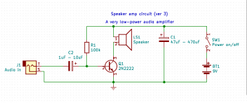
And that brings us to the attached schematic, version #3 of the circuit you've been building. The only change from version 2 (which could only click) is the added capacitor to the base, and the added input jack, so you can plug the signal from your guitar pedal into it.
That tiny change makes a huge difference: the circuit goes from only being able to make a little "click!", to being able to actually make sound, in fact, a copy of the sound from your guitar.
It won't be loud - it will be much quieter than your LM386 amp that never worked right - but it is in fact a working amplifier, and one simple enough that you should be able to wrap your brain around the function of every component.
Try it...add the base coupling cap and input jack, feed it with either your guitar via FX pedal, or from an MP3 player or something. Keep the FX pedal or MP3 player turned down to zero at first, turn it up gradually. You should hear the music through the speaker, though fairly quietly. Turn up too far, and it will distort. Turn up some more, and you might fry the wee little 2N2222. Your call if you want to try that or not...
-Gnobuddy
Attachments
This isn’t a good amplifier circuit. It has no DC stability and runs DC through the speaker at wildly varying currents depending on transistor beta. It will have little gain and much distortion. Get Bob Cordells book and the art of electronics as a good start.
This isn’t a good amplifier circuit..... Get Bob Cordells book....
Read the thread. Jimbo is very inexperienced. Gnobuddy is trying to TEACH. From rock-core basics. I'm fascinated. I suspect Gnobuddy should wrap it up as a book. The book to read BEFORE BC and AoE.
I will need to read this a few times to get all of it.
With the 2nd resistor and audio-in jack, I can hear my guitar faintly thru the speaker. I also can play music from my iPhone up to full phone volume, which produces sound a little louder than my guitar but still quite faint. The 2N2222 gets very hot with my phone all the way up. The circuit still works after I give the 2N2222 time to cool down, so I guess I haven't fried it.
If I understand correctly, the audio signal travels as (or on) AC, but DC also is used in this circuit. Does the transistor simultaneously process both DC and AC? It does indeed appear as if Magic is at work here.
Last edited:
All true (though if you calculate the numbers, you'll find the wildly varying DC current is low enough to cause no damage to speaker or transistor even for a maximum-beta sample.)This isn’t a good amplifier circuit. It has no DC stability and runs DC through the speaker at wildly varying currents depending on transistor beta. It will have little gain and much distortion.
Just a few days ago, I read this free book about the Wright Brother's engines, as used in their "flying machines": The Project Gutenberg e-Book of The Wright Brothers' Engines and their Design; Author: Leonard S. Hobbs.
The engine that the Wrights used for their 1903 first powered flight had no counterweights on the crankshaft - the Wrights didn't even realize that the reciprocating mass of the pistons would shake the engine! The intake valves were just spring-loaded, and sucked open by the piston's intake stroke - they were not actuated by a cam. Maximum rpm was only about 1000. There was no throttle, and the engine ran at full power the entire time it was on!
You might very correctly say: this wasn't a good engine. It had too much weight and made too little power. It ran the propeller at wildly varying RPM depending on air temperature.
But that bad engine did the most incredible thing: it lifted the Wright Brothers off the ground (with a little help from a headwind and a falling weight), kept them in the air for a few precious seconds, and landed them permanently in the history books. It did exactly what it was supposed to do.
And this bad amplifier has just done a similarly incredible thing: it's lifted Jimbo off the ground, figuratively speaking, and given him his first working audio amplifier. It too has done exactly what it was supposed to do. 🙂
-Gnobuddy
For sure. We humans were walking around on this planet for some 150,000 years before somebody made the first transistor amplifier. It's that complicated a concept - it took that long to figure out!I will need to read this a few times to get all of it.
The amazing thing is that, thanks to the genius of those who came before us, you can understand this in a few days or weeks, instead of a couple of hundred thousand years. 🙂
Congratulations! You've just built your first properly working amplifier!With the 2nd resistor and audio-in jack. I can hear my guitar faintly thru the speaker. I also can play music from my iPhone up to full phone volume.

And it's not doing strange and annoying things - no hum, no intermittent silence. It's a crude, simple, and flawed amp for a variety of reasons - but you built it, from a schematic diagram no less (not from pictures), and it WORKS! How cool is that?
Yes, that can definitely happen. The reason is that the 2N2222 is a small-signal transistor, and it was never really designed to do the heavy lifting needed to make loud noises from a loudspeaker.The 2N2222 got very hot with my phone all the way up. The circuit still worked after I gave the 2N2222 time to cool down, so I guess I didn't fry it.
But - its cheap, its slim leads fit in a breadboard, it's slow enough to remain stable even on a breadboard, and so you got a taste of success, finally. 🙂
-Gnobuddy

Sorry, I missed this the first time.If I understand correctly, the audio signal travels as (or on) AC, but DC also is used in this circuit. Does the transistor simultaneously process both DC and AC?
You're perfectly correct. Transistors can't work on AC (which reverses direction, i.e. swaps (+) and (-), frequently). They really can only work on DC.
But we can make that DC vary. Never actually reversing, but instead fluctuating between a small and a big value. This means there is some sort of average one-way (DC) current, but there are fluctuations riding on it (AC). A simultaneous mix of AC and DC.
And that's what we've done here. The 9V battery supplies DC. The 100k resistor supplies a small DC current to the base of the transistor, which responds by supplying a larger DC current to the loudspeaker.
Next, the input coupling capacitor feeds AC from your MP3 player to the transistor base. This small AC signal "wiggles" the DC current coming from the 100k base resistor up and down - it never actually reverses, it only fluctuates in strength while always flowing in the same direction.
Finally, the transistor amplifies that fluctuating base current and feeds it to the speaker. So the former steady (DC) current through the speaker now fluctuates according to the signal from your MP3 player, and the speaker cone moves accordingly. And you hear sound.
As famous science-fiction author Arthur C. Clarke once wrote, "Any sufficiently advanced technology is indistinguishable from magic."It does indeed appear as if Magic is at work here.
Arthur C. Clarke may have been a very twisted human being ( Talk:Arthur C. Clarke/Archive 1 - Wikipedia ), but he was also a visionary genius, and certainly I think this particular statement by him is spot-on.
Can you imagine the reactions if you took a little pocket GPS unit back to, say, 1920, a mere century ago, and showed people how this device the size of a pack of cards could not only tell you exactly where you were on earth, but also speak, and direct you to a faraway destination? Magic!
Can you imagine how shocking the first steam locomotive would have been to those who saw it? A machine that moved itself along on the ground, without horses or humans pulling it?
And Edison's first phonograph: how eerie would it have been to hear a human voice coming out of a machine?
For me, the magic has never completely gone out of many of these incredible inventions. I know very well how the wings of an aeroplane generate lift, but it's still magic to me every time I look up and see a jetliner, a hundred tonnes of metal magically suspended in thin air...how can it possibly be?
-Gnobuddy
Next, the input coupling capacitor feeds AC from your MP3 player to the transistor base. This small AC signal "wiggles" the DC current coming from the 100k base resistor up and down - it never actually reverses, it only fluctuates in strength while always flowing in the same direction.
Oscilloscopes are too expensive for me (although Arduino versions may be within reach), but I have perused a few instructables on their construction, and your explanations make me wonder:
Does flat/un-"wiggled" DC appear as a straight line on an oscope?
Does the wiggling DC current appear as a wave?
Does that wiggling DC appear entirely above the "midline" of the oscope, such that one may want to adjust/scroll the wave down to the midline?
Yes, a straight horizontal line. Voltage is on the y-axis, time on the x-axis, so mathematically speaking, you are looking at the graph of the equation V=constant, which, if you recall your high-school coordinate geometry, is a straight horizontal line. 🙂Does flat/un-"wiggled" DC appear as a straight line on an oscope?
Exactly! AC, riding on DC, which shifts it above (for positive DC) or below (for negative DC) the V=0 line. A wiggly line, not centred on the x-axis, but instead either raised above it, or dropped below it.Does the wiggling DC current appear as a wave?
Does that wiggling DC appear entirely above the "midline" of the oscope, such that one may want to adjust/scroll the wave down to the midline?
While you certainly can scroll an AC+DC signal up or down to centre it on the x-axis, every proper oscilloscope has a hardware feature that does this automatically for you. There will be a button on the front that lets you select either "AC coupling" or "DC coupling".
In DC coupling mode, the incoming signal is displayed exactly as it is, i.e. offset from zero if there is in fact DC mixed in with AC.
In AC coupling mode, the oscilloscope uses an internal coupling capacitor (just as we did in your 2N2222 amp) to strip away the DC from the AC. So in this mode, you only see the AC wiggles, and the DC is removed; the AC is always centered on the zero-volts line.
This is incredibly useful when you're trying to see, for example, 100 mV of guitar audio signal riding on 200 volts DC at the anode of a valve (vacuum tube.) The AC is tiny and the DC enormous in this case, so if you looked at the combined signal, you wouldn't even see the tiny, tiny wiggles riding on top of the huge DC voltage.
Speaking of oscilloscopes, there are various lower-cost alternatives, of varying levels of usefulness. The cheapest is to find free software that turns the sound card in your computer into an audio-only oscilloscope that displays the waveform on your computer screen.
This sort of "'scope" has a number of limitations. It cannot "see" DC at all, and it can only respond to frequencies the sound card can cope with (typically 10 Hz - 20 kHz). There is no calibration, so you don't know if you're looking at 1 mV or 10 mV or 50 mV. The sound card has a low input impedance (a more advanced concept for you to research), and this can "load down" the signal you're trying to view. The sound card can be damaged if the incoming signal is too big for it, and if it's built into your computer motherboard, that means your computer is damaged permanently.
So I'm not a big fan of the "sound card oscilloscope" idea, but in a pinch, and as long as you're careful to stay within its severe limitations, it may be better than nothing at all.
Not long ago I bought a wonderful little USB 'scope made by a company called Syscomp (CircuitGear Mini – Syscomp Electronic Design) for a measly $65 (USD). It packs a lot of good features into a compact little package, and avoids most of the limitations of the soundcard oscilloscope approach. Sadly, Syscomp's founder passed away in 2017, and the company appears to be moribund now; the website lists every Syscomp product as "no longer available". What a pity. 🙁
-Gnobuddy
I basically have the LM386 amp working with too much noise to justify spending any more time on this. Thank you kindly for being so patient with this total noob. In short, I need a real preamp. The stomp box that I’ve been using does raise the signal strength enough for the LM386 to use it, but the stomp box itself causes most of the noise when I can hear the guitar.
Googling “DIY guitar preamp” found some really simple designs, but they are quite old. Others looked pretty complicated. Any recommendations for a simple solid state preamp for electric guitar? Emphasis on simple and solid state. Oh, and something that may clean, clarify, or “condition” (?) the signal for a downstream power amp, if that kind of thing wouldn’t make the design too insanely complicated for a noob.
FWIW, I’ll want to energize the preamp with a 12V wall wart.
Last edited:
Did you look at the ruby?? It’s just lm386 with jfet preamp section and dead simple. I am quite happy with mine as a play at home/recording amp. It breaks up surprisingly pleasantly as well.
I know this isn't what you asked, but have you attempted to find out why the LM386 amp is too noisy? And/or why the preamp is so noisy?I basically have the LM386 amp working with too much noise to justify spending any more time on this.
If the noise is caused because the LM386 is not in a grounded metal box, the noise will remain, no matter what preamp you use. The fix is obvious - put the power amp in a grounded metal box! (I mentioned this many, many posts ago, but I don't recall any response from you.)
If the noise is caused because one or both of the switching power supplies is noisy, the noise will remain no matter what preamp you use. Have you done anything to test for this possibility? (Simplest: run both the preamp and the power amp from 9V batteries, see if the hum problem remains.)
If the noise is caused because neither guitar, nor preamp, nor power amp is grounded, the noise will remain no matter what preamp you use. Clue: hum will drop substantially when you touch the guitar strings with your hand. Better clue: ground the thing temporarily to a real ground, such as the metal housing of an existing (and properly wired) household appliance, see if hum drops.
The scattershot approach rarely works in electronics. If you pin down the source of the problem, you can fix it. Otherwise you might go to all the trouble and expense of building / buying a new preamp, and still have the same noise problem as before, because the preamp was never the source of the problem in the first place.
You're very welcome. Glad I could help!Thank you kindly for being so patient with this total noob.
Is the stomp-box noisy when plugged into a commercial amplifier or guitar amp? If not, the problem isn't the stomp-box.In short, I need a real preamp. The stomp box that I’ve been using does raise the signal strength enough for the LM386 to use it, but the stomp box itself causes most of the noise when I can hear the guitar.
Is the stomp-box noisy when powered with a 9V battery (and not a power supply)? If not, the wall-wart power supply is the source of the problem, not the stomp-box itself.
Remember, the stomp-box adds more gain to the circuit. Adding gain to a noisy circuit will make existing hum and noise more audible. I think this is what's happening; I don't think the stomp-box is the source of the noise, I think it's revealing the noise caused by your unshielded, ungrounded, and possibly unstable, LM386 amp.
I can help you piece something together (we can use your existing knowledge of 2N2222 amplifiers to give you a head-start.)Any recommendations for a simple solid state preamp for electric guitar? Emphasis on simple and solid state.
You should know in advance that there is pretty much no such thing as a really good-sounding DIY solid-state preamp; you can build something that makes a guitar-like noise, but it won't usually give you great guitar tone.
But first, I really encourage you to do some detective-work. Is the guitar pedal really the source of your hum and noise? Personally, I very much doubt it, because a pedal that bad wouldn't have made it into production. (Google "name of your pedal + hum"; are other users complaining that the pedal hums and is noisy? Plug the pedal into your Marshall amp; is it noisy?)
So I don't think it's the pedal, I think it's something else - most likely one of (a)bad grounding (b)bad power supply (c) lack of shielding around the power amp.
There really isn't such a thing. What you need is to keep the signal from being mauled in the first place; it isn't really practical to maul a signal, and then un-maul it with fancy electronics (maybe if you have the CIA's resources, but you and I don't.)Oh, and something that may clean, clarify, or “condition” (?) the signal for a downstream power amp, if that kind of thing wouldn’t make the design too insanely complicated for a noob.
So I'll say again, the thing to focus on is, why is the signal getting mauled in the first place? That's the thing to find, and fix.
-Gnobuddy
The MPF 102 JFET in the Ruby has been out of production for a long time, and is no longer available at Mouser or Digikey.I’ll look at the Ruby. Thx.
Perhaps you might find some somewhere on the 'Net, at a surplus store or auction site, but it might take some searching.
The Ruby amp puts a single JFET ahead of a standard LM386 amp. I can show you how to achieve much the same effect with one or two of the 2N2222 transistors you already own.
There are some advantages to the JFET, but the 2N2222 will make a good enough replacement with a little care in design.
It will be interesting to see how adding a pre-amp stage affects the hum / buzz / noise / stability problems the LM386 amp is exhibiting now.
-Gnobuddy
Last edited:
Thanks, Gnobuddy, you are absolutely right. You gave me a lot of good steps to locate the source of the hum/noise. I was planning to return to that post when I got the basic functionality again, but I became very frustrated. Now that I’ve had a chance to catch my breath again, I’m going to return to the hum/noise problem. But first I will change things around a bit to follow the “Ruby” LM386 as closely as possible. I’ll have to look for a replacement. I do have a few 2N2222s, but that thing got really hot. How would I use that transistor without frying it?
Last edited:
According to J113 JFET – Replaces MPF102 – Genuine Fairchild – GuitarPCB , the J113 is a “perfect” replacement for the MPF102. I’m a little dubious of such claims after the NTE283, but at least it won’t cost an arm and leg to give it a try.
Last edited:
- Home
- Live Sound
- Instruments and Amps
- Why does this LM386 breadboard not work as a guitar amp?