Sounds like a plan! At least the "Ruby" schematic on the Runoff Groove website shows a 100uF filter cap between +9V and ground; a cap like that is mandatory for all audio amp circuits.But first I will change things around a bit to follow the “Ruby” LM386 as closely as possible.
With chip amps, it's a really, really good idea - mandatory, really - to put a relatively small-value ceramic or film capacitor - something like 0.1uF - right across the two power pins, or as close as you can get. That's between pins 6 and 4 for the LM386. Without that cap, most audio chips will turn into radio transmitters instead of audio amplifiers.
I'll show you. It won't get hot this time (as long as it's wired properly), I promise.I do have a few 2N2222s, but that thing got really hot. How would I use that transistor without frying it?
The 2N2222 got really hot when driven hard in your first successful amplifier build, because it was being asked to do more than it was ever designed to do. It is a small-signal transistor, and was never designed to drive a loudspeaker.
But, as we've discussed before, I had my reasons for choosing it - and it did its job. It got you to the point of building a working amplifier, and that will come in very handy again soon.
Have you got Ohm's Law, and the equations that describe electrical power in a resistor, under your belt yet? If not, it's time to study up, and start thinking about it. (Hint: would the 2N2222 have become hot if your loudspeaker had a resistance of 8000 ohms instead of 8 ohms?)
In case you've forgotten, Volume I of the six free textbooks at the All About Circuits website ( Textbook for Electrical Engineering & Electronics ) contains everything you need. Chapters 1 and 2 (Basic Concepts and Ohm's Law respectively) will clear up some of the fog immediately, and if you work all the way through volume 1 (this will take lots of time!), a lot of things will start to make more sense.
-Gnobuddy
So far I have not tried to do anything with Ohm's law because, frankly, I would't know how to use it. For example, given a measured voltage on the front of a resistor and the value of the resistor, I can divide the former by the latter to get the current. Now what? What do I do with that number? When is it relevant to something I am doing? Or suppose I calculate resistance by dividing voltage by current, now what? Do I want to use a resistor that is less than, equal to, or greater than that number? And if it is sometimes <, sometimes =, and sometimes >, when is which and to accomplish what? If I want to use a value < or > than the calculated resistance, by how much? It seems that before I can begin to know how to use Ohm's Law practically, I would need to know a lot about physics and how these variables and choices affect each other and fit together. I have bookmarked that textbook series and registered with that site, but I'm unsure that delving into the math is the best use of my time. At this time, it probably makes the most sense to build the Ruby (J113 delivery expected by week end), hunt down the cause of the hum/noise (if it still exists) and fix it, and also try the various Ruby mods for a better understanding of what they do. For now, I'm still in the early parts of the Anderton book. Thank you again for that link.
One of the things I like about Platte's Make: Electronics is the use of many examples/experiments to show the many things that combined components can do. Learning by doing is a good method for me. However, I draw the line at Mr Cavendish's highly personal measurements: "In January 1781, before Georg Ohm's work, Henry Cavendish experimented with Leyden jars and glass tubes of varying diameter and length filled with salt solution. He measured the current by noting how strong a shock he felt as he completed the circuit with his body. Cavendish wrote that the 'velocity' (current) varied directly as the 'degree of electrification' (voltage)."
One of the things I like about Platte's Make: Electronics is the use of many examples/experiments to show the many things that combined components can do. Learning by doing is a good method for me. However, I draw the line at Mr Cavendish's highly personal measurements: "In January 1781, before Georg Ohm's work, Henry Cavendish experimented with Leyden jars and glass tubes of varying diameter and length filled with salt solution. He measured the current by noting how strong a shock he felt as he completed the circuit with his body. Cavendish wrote that the 'velocity' (current) varied directly as the 'degree of electrification' (voltage)."
Last edited:
Chicken and egg...you need to know it before you can use it, no?So far I have not tried to do anything with Ohm's law because, frankly, I would't know how to use it.
Let's say the volume control on your amplifier is adjusted to put out 1 volt AC of audio signal at the amp output. You have a 4 ohm speaker, and an 8 ohm one. If you connect one speaker and then the other to your amp, which one will draw more current? How much more?For example, given a measured voltage on the front of a resistor and the value of the resistor, I can divide the former by the latter to get the current. Now what? What do I do with that number?
When is it relevant to something I am doing?
Which speaker will draw more power? How much more? Which one is more likely to overheat the amplifier?
What would probably happen if you tried to use a 1-ohm speaker? How about a 0.1 ohm speaker?
Based on your answers, what do you think is the reason nobody makes 0.1 ohm speakers?
Your amp used a 10k pot. Why doesn't it use a hundred million ohm pot? Why doesn't it use a 0.00001 ohm pot? Why does nobody even manufacture those pot values?
You can answer most of these questions if you know Ohm's law, and the equation that connects power, voltage, and current. You can answer the rest if you combine Ohm's law and some understanding of the abilities of electronic components.
Every one of the answers is entirely relevant to what you're trying to do: build an amplifier, understand how it works, keep it from burning up, and keep the battery from melting and catching fire.
Only you can choose the most personally satisfying path on your electronics journey, and decide what to learn, and in what order. But I promise you, learning Ohm's law and its implications won't be a waste of time. 🙂
-Gnobuddy
Every one of the answers is entirely relevant to what you're trying to do: build an amplifier, understand how it works, keep it from burning up, and keep the battery from melting and catching fire.
OK, I'll try to answer those Qs tomorrow after I've recharged. The "see if it explodes" approach has some shortcomings. It would be nice to have a reasonable understanding of what to expect.

I think that's why it's not very popular any more with bridge-builders and aircraft designers. 😀The "see if it explodes" approach has some shortcomings.
Merry Christmas to everyone on the thread!
-Gnobuddy
I knew this existed but I had trouble finding it: EPFM Book | General Guitar Gadgets
Also: http://www.geofex.com/FX_images/anderton.gif
Also: http://www.geofex.com/FX_images/anderton.gif
Merry Christmas!
I can't afford an oscilloscope for this hobby. I have an iOS app called EE-Pro, which includes a function generator. I may be wrong but, as I understand it, that is essentially a "signal generator." I suspect I can inject the signal into the 1/4" guitar plug (using a chain of 2 unpowered adapters). Is there an economical way to trace the signal thru the circuit to determine at which stage(s) the signal is substantially degraded, without an oscilloscope?
There's almost certainly an app that can use an iPhone microphone to listen to sound output (from a handheld tracer?) and generate a wave. However, I would be content to hear the signal as it would sound if emitted at each circuit stage tested, if that's possible or even makes sense.
Last edited:
Yes. Somewhat ironically, a little battery-powered LM386 chip amp connected to a small speaker makes a good audio signal detector. 😀Is there an economical way to trace the signal thru the circuit to determine at which stage(s) the signal is substantially degraded, without an oscilloscope?
There are plenty of small, cheap audio power amp boards available today (on Amazon, Ebay, etc) that would also work well for this.
I've heard the idea before, but personally, I'm leery of the idea of using very expensive phones as signal generators or detectors ('scopes). If something goes wrong, you could fry something inside the phone.
I started doing electronics when I was still in elementary school, so I had zero money and zero test equipment - not even a multimeter - for many years. Back then, a decent 20k/volt multimeter represented wealth beyond my dreams, something I couldn't even aspire to own.
Stubborn persistence took me a long way, until eventually I made my own signal generator (a two-transistor oscillator to generate a test tone), and signal detector (a little discrete audio amp.) Later I made a DC voltmeter of sorts using a 741 op-amp (it compared the incoming DC voltage to an internal reference voltage, and you turned a knob until the two were equal, at which point you could read the voltage off the knob.)
Times have changed, and now you can get a DMM for $5 at places like Harbor Freight, so these days nobody needs to work completely blind. You can go quite a long way with a DMM, and, as you're proposing, a signal generator and a signal detector of some sort.
-Gnobuddy
Somewhat ironically, a little battery-powered LM386 chip amp connected to a small speaker makes a good audio signal detector. 😀
The LM386 datasheet includes the attached schematic for a Square Wave Oscillator. There is also a more complicated schematic for a "Low Distortion Power Wienbridge Oscillator." Are such oscillations typically audible, or are they useful only with a scope plotting waves?
I'm a little hesitant to try to use an LM386 signal generator - most likely suffering from hum/noise - to test an LM386 amp suffering from hum/noise.
Attachments
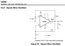
There are two parts to the plan: one, an oscillator (to make a small audio AC signal voltage), and two, an amplifier/speaker acting as an audio detector, so you can hear the test signal from the oscillator at various points in your circuit.The LM386 datasheet includes the attached schematic for a Square Wave Oscillator.
IMO the LM386 amp is most appropriate for the second role, as a detector. However, you certainly can tie its hands behind its back and make it into an oscillator if you want to.
You can also make a test oscillator with - tah dah - two 2N2222s, a few resistors, and a few caps, if you like.
Other easy oscillator options include the old (but still useful) 555 timer IC, as well as any of a variety of op-amps.
There is also the option of using an MP3 player or something as your test signal source - it doesn't have to be an oscillator, just something you can hear. (But, as discussed before, there is some inherent risk to the MP3 player, if things go badly wrong.)
They're audible if you pick a frequency that's in the audio range, and which is easily reproduced by whatever speaker / headphone you're using to listen to it.Are such oscillations typically audible, or are they useful only with a scope plotting waves?
The frequency of a Wien Bridge oscillator is set by the value of two resistors and two capacitors in the circuit, so you can pick values to get the frequency you want.
For Hi-Fi circuits, 1 kHz is the typically used frequency. It's a very annoying frequency to listen to, however. For guitar, which has smaller bandwidth requirements than Hi-Fi, a frequency around 300 Hz is usually a good choice. It's less annoying than 1 kHz to listen to.
That's why I used the word "ironically". 🙂I'm a little hesitant to try to use an LM386 signal generator - most likely suffering from hum/noise - to test an LM386 amp suffering from hum/noise.
One more thing to keep in mind: the LM386 circuit is so simple that there aren't a lot of places to probe for an audio signal. I can only think of three - the two audio input pins, and the audio output pin.
Also, this sort of signal tracing will tell you if the signal is interrupted at some point - but I'm not sure it will help you find out where hum is entering your circuit.
By the way: does your LM386 amp hum when you connect an MP3 player to its input, instead of your guitar and FX pedal?
-Gnobuddy
There is also the option of using an MP3 player or something as your test signal source - it doesn't have to be an oscillator, just something you can hear. (But, as discussed before, there is some inherent risk to the MP3 player, if things go badly wrong.)
What if I ran the iPhone signal through a diode, before it gets to the JFET preamp chip? Would it be solely DC between the iPhone and JFET? Does the AC surfer start riding the current downstream?
One more thing to keep in mind: the LM386 circuit is so simple that there aren't a lot of places to probe for an audio signal. I can only think of three - the two audio input pins, and the audio output pin.
I was thinking I could also test before and after every cap and resistor. Might the results suggest a need for different values at certain points in the circuit? This is probably confused thinking.
By the way: does your LM386 amp hum when you connect an MP3 player to its input, instead of your guitar and FX pedal?
Yes. However, I'm not sure I had the simplest circuit possible at that time. When I receive my order including JFETs, I plan to rebuild a la Ruby.
A diode is the equivalent of a one-way valve, like the one that lets air into your car tyre, but not back out....I ran the signal through a diode...
So a diode lets only half of the AC through - depending on which way you orient it, it will either let only positive half-cycles of current flow, or only negative half-cycles.
In either case, you end up with a current that never actually reverses (so it's not AC), but it's not a constant flat line either - it's fluctuating between zero and some maximum value.
We've encountered this particular beast before, so we should recognize it for what it is: a mixture of AC and DC.
So if you feed pure AC through a diode, what comes through the diode is a mixture of AC and DC. The AC waveform has also been distorted (half of it lopped off.) Not good if it's music you want to listen to; may be okay if it's a guitar signal you *intend* to distort the heck out of.
This tutorial might be helpful: https://www.electronics-tutorials.ws/diode/diode_5.html
Also: the diode will not necessarily protect the iPhone from damage, in the event things go badly wrong.
You could, and it might catch any defective capacitors, but those are quite rare.I was thinking I could also test before and after every cap and resistor.
Our ears make really lousy test instruments when it comes to quantitative measurements. I won't say this is impossible - certainly many classic guitar amps have had capacitor values tweaked entirely by ear to achieve a certain sound - but I don't think it's a particularly reliable circuit design method.Might the results suggest a need for different values at certain points in the circuit? This is probably confused thinking.
This is one of the reasons why it's wise to distrust the "golden ears" audiophile types. Almost certainly, their ears are no better than average (they never provide proof of their superiority), the things they claim to hear don't actually exist, and if they do exist, test equipment will reveal them more clearly than the human ear ever will.
Fair enough!Yes. However, I'm not sure I had the simplest circuit possible at that time. When I receive my order including JFETs, I plan to rebuild a la Ruby.
Remember: there should always be a big fat electrolytic cap across the battery power and ground lines, say 47uF - 470 uF, within a few inches of the LM386 power pins (6 & 4); and there should always be a ceramic or plastic film cap (typically 0.1 uF) as close as possible to the LM386, wired to the power and ground pins (6 & 4).
The Ruby schematic on Runoff Groove shows the former, but not the latter. Don't forget to add it. It is necessary with virtually every kind of audio chip.
-Gnobuddy
Sounds like a plan! At least the "Ruby" schematic on the Runoff Groove website shows a 100uF filter cap between +9V and ground; a cap like that is mandatory for all audio amp circuits.
With chip amps, it's a really, really good idea - mandatory, really - to put a relatively small-value ceramic or film capacitor - something like 0.1uF - right across the two power pins, or as close as you can get. That's between pins 6 and 4 for the LM386. Without that cap, most audio chips will turn into radio transmitters instead of audio amplifiers.
I'll show you. It won't get hot this time (as long as it's wired properly), I promise.
The 2N2222 got really hot when driven hard in your first successful amplifier build, because it was being asked to do more than it was ever designed to do. It is a small-signal transistor, and was never designed to drive a loudspeaker.
But, as we've discussed before, I had my reasons for choosing it - and it did its job. It got you to the point of building a working amplifier, and that will come in very handy again soon.
Have you got Ohm's Law, and the equations that describe electrical power in a resistor, under your belt yet? If not, it's time to study up, and start thinking about it. (Hint: would the 2N2222 have become hot if your loudspeaker had a resistance of 8000 ohms instead of 8 ohms?)
In case you've forgotten, Volume I of the six free textbooks at the All About Circuits website ( Textbook for Electrical Engineering & Electronics ) contains everything you need. Chapters 1 and 2 (Basic Concepts and Ohm's Law respectively) will clear up some of the fog immediately....
No, I haven't forgotten. My eyes tend to glaze over when I read anything that includes math. The use of "I" for amps and "E" for volts infuriates me and makes it even harder for me to read anything about the math. I did well in math thru Calculus 1 but dropped out of Calculus 2 after spending more than an hour working -- Dr's office called & said to go to Urgent Care ....
I'm alive. I dropped out of Calculus 2 after spending more than an hour working a single problem, involving trig substitutions, to rotate a curve on a graph. Be that as it may, I will accept the math challenge. A=V/R; V=AxR; R=V/A. I don't remember the formula for watts [see P.S.].
If R goes from 8 to 8000, then ceteris paribus A=V/1000R, and V=1000xAxR, meaning voltage (akin to pressure) increases 1000x and amperage (flow) drops to 1/1000th of its original value. I'm not sure what the net effect of those changes to A and V is. I'm inclined to think it should all balance out in the end, but that the required increase to the voltage ratings of the components is impractical, so the voltage increase would exceed the component ratings as a practical matter and KABOOM! The voltage increase should make the transistor even hotter, but the huge decrease in amperage/flow might offset that and cause no change. Frankly, I just don't know what the net effect would be.
P.S. W=VxA. (I believe I've seen watts described alternatively as voltamps.) If V increases by 1000x and A decreases to 1/1000th, W=1000Vx(A/1000), which simplifies to W=VxAx(1000/1000) which is back to W=VxA. In other words, the power (work force) is unchanged despite the huge increase in voltage, given the corresponding decrease in amperage. Still, we have the residual issue with the required voltage rating being impractical. Conversely, if R goes from 8 to .008, then A increases 1000x and V decreases to 1/1000th of its original value. The required voltage rating would not be a problem; the required amperage rating might become impractical; but the power (work force) would be unchanged. To answer your Q in a later post, the impracticality of huge changes to the speaker resistance, in either direction, lies in the effects on the ratings of other components relative to V and A. The standard speaker resistance values appear to be moderate ohms allowing for reasonable V and A component ratings. A nice balance of nature.
Last edited:
Amazon.com: ********: A Theory (8601411248108): Aaron James: Books
Editorial Reviews
...
“Importantly, [James makes] us confront a crucial question, which, I believe, we ask ourselves all too infrequently: How much of an ******* am I?”
—Alex Balk, Slate
Editorial Reviews
...
“Importantly, [James makes] us confront a crucial question, which, I believe, we ask ourselves all too infrequently: How much of an ******* am I?”
—Alex Balk, Slate
Last edited:
I suggest you leave the clincal diagnoses to those qualified to make them. 🙂
Here's another good medical term you should know: Illusory superiority - Wikipedia
-Gnobuddy
FWIW, everything worthwhile that I've ever learned, took much longer than an hour to learn. MUCH longer!I'm alive. I dropped out of Calculus 2 after spending more than an hour working a single problem <snip>
Malcolm Gladwell (author) made a study of people who were outstandingly good at whatever it was they did, and found a common factor: each of them had spent at least 10,000 hours getting good at their chosen speciality. The equivalent of twenty hours a week, for ten years, more or less.
Gladwell's book was called "Outliners: The Story of Success", and was a best-seller.
Almost; you could not simultaneously both get a 1000-fold increase in voltage, and a 1000-fold decrease in current! If you hold the voltage constant, you get the 1000-fold reduction in current. If you hold the current constant, you get the 1000-fold increase in voltage.If R goes from 8 to 8000, then ceteris paribus A=V/1000R, and V=1000xAxR, meaning voltage (akin to pressure) increases 1000x and amperage (flow) drops to 1/1000th of its original value.
If you go back and look at the problem I posed, it specified that your amplifier was adjusted to produce a fixed, constant, unvarying amount of AC voltage. This means that when you increase the resistance a thousand times, you would decrease the current a thousand times.
This wasn't a random exercise; with the volume knob set, modern power amplifiers do tend to behave like fixed voltage sources.
That being the case, what happens if you change from an 8 ohm to a 4 ohm speaker? Remember, the amplifier attempts to produce the same voltage in both cases.
That's it. 🙂"Why do you think nobody sells 0.1 ohm speakers?"
<snip>
...the required amperage rating might become impractical;
If you tried to use a 0.1 ohm speaker with an amp running at reasonable supply voltage, the amplifier would have to supply impractical amounts of current. Ergo, we do not have 0.1 ohm speakers.
No...voltage is the same as before, current is much higher, so the power is vastly increased.but the power (work force) would be unchanged.
Exactly! 😀To answer your Q in a later post, the impracticality of huge changes to the speaker resistance, in either direction, lies in the effects on the ratings of other components relative to V and A. The standard speaker resistance values appear to be moderate ohms allowing for reasonable V and A component ratings. A nice balance of nature.
The balance is not so much with nature, as with the nature of current technology, which changes with time. In the vacuum tube era, "normal" meant thousands of ohms, dictated by the very small currents and very high voltages that vacuum tubes operated at. In the earlier transistor era, "normal" meant a few ohms, because that suited the high current, low voltage capabilities of silicon power transistors.
That has changed again in recent years, now that we have MOSFETS that can handle tens or even hundreds of amperes of current, while operating on just a few volts. The power supply in your desktop computer often supplies tens of amperes at a voltage of 3.3 V or less, equivalent to a fraction of an ohm load.
However, audio is an old technology, and those recent changes have not affected it much. Yet. So, still no 1 ohm speakers, or amplifiers designed to drive them.
By the way: there is very good reason NOT to use the letter "A" to mean "current", while simultaneously using the same letter "A" to mean "Ampere", the unit of current. Let's suppose we want to write the mathematical equation describing the situation "Current A has a strength of 5 amperes."
The corresponding equation would be: A = 5 A
Algebraically, this means something entirely different: it is the same as equation (x = 5x), which means "The quantity x equals five times itself". The solution is x=0, or A=0!
So "A = 5 A" is an atrociously poor way of writing down an equation for current.
It would have made sense (in English) to use "C" for "current", but "C" was already taken - for capacitance, which was discovered before electric current was. "I", I think I read, was borrowed from a different language; early discoveries in electricity came from Italy, Germany, and many other non-English-speaking countries.
Ultimately, using "I" for current is a convention, no better or worse than a country choosing to drive on the right side of the road, or the left...
For the same reason "A" is a bad choice for a variable to represent "current", I much prefer using "E" for a voltage, or "U", as is done in much of Europe. Anything but "V", which leads to mathematical absurdities such as "V = 10V", once again, an algebraic equation with the solution V = 0. Not at all what it is supposed to mean!
-Gnobuddy
FWIW, everything worthwhile that I've ever learned, took much longer than an hour to learn. MUCH longer!
Re rotating graphs, I grasped the principal immediately but was annoyed to be required to provide the detailed proof that I understood. Clearly, my confusion re voltage - thinking I had held it constant while actually allowing it to increase 1000x - shows I still need to write down the proof. I guess all those math teachers and profs - it pains me immensely to admit this - knew what they were doing.
what happens if you change from an 8 ohm to a 4 ohm speaker? Remember, the amplifier attempts to produce the same voltage in both cases.
Assuming constant E (voltage), R goes from =E/4 to =E/8, for a 50% decrease. ... Duh! That's what you changed. ... The thing to calculate is amps. Assuming constant E, I goes from =E/8 to =E/4, for a doubling of amperage. With one value in Ohm's Law constant, the other two vary inversely to each other.
... A = 5A ... V = 10V ...
Good point. A constant can't be a variable. I would have caught that back in the day.
Last edited:
I received my big order and will start building later today. In the meantime, I am wondering about the quality of my workspace. To be more specific, I have been working at my computer desk, surrounded by a laptop, big monitor, lots of computer peripherals, and many surge protectors, power cords and USB cables. All this stuff is spread across several circuits connected to different breakers at the main panel on the side of my house. On the one hand, I suspect this may be a very dirty environment contributing to hum/noise previously. On the other hand, if I can overcome the potential challenges of this environment, that would be a good thing. Any thoughts about a workspace like this and whether it is reasonably feasible to overcome any challenges that it poses?
Last edited:
- Home
- Live Sound
- Instruments and Amps
- Why does this LM386 breadboard not work as a guitar amp?