The environment isn't ideal, but I have a little Lepai class-D chip amp sitting on top of my wife's desktop PC, driving a pair of bookshelf speakers. It's in a grounded metal enclosure, as all audio amplifiers should be for best results, and I can hear no audible problems with it at all. (The speaker quality is the limiting factor, not the amp.)Any thoughts about a workspace like this and whether it is reasonably feasible to overcome any challenges that it poses?
If you look back through the thread, you experienced a lot of intermittent problems - the amp would work one moment, and not the next, with no identifiable cause that you could discern.
I'm hoping that your gradually increasing experience has altered this, and your latest attempts are at least consistent. Consistent hum, you can attempt to address. An amplifier that stops working every few minutes, you cannot.
It will be interesting to see what the JFET does to your existing hum problem. As used in the Ruby amp, the JFET has unity voltage gain (so it won't boost hum), but it also has a much higher input impedance than your LM386 amp (which tends to pick up more hum and noise.)
-Gnobuddy
... in a grounded metal enclosure ...
First thing: crawl under my computer desk and pull a ground wire from the wall. Or from one of the surge protectors, for some isolation.
The metal PC case is grounded, and conveniently on top of the desk...First thing: crawl under my computer desk and pull a ground wire from the wall. Or from one of the surge protectors, for some isolation.
It may turn out to be a noisy ground, but it's easy to try it and find out.
-Gnobuddy
I built the Ruby today and got it working. With a 9V battery and my iPhone as the music source, the sound (thru a crappy speaker) is clean with virtually no hum/noise. With my Les Paul plugged in and all knobs (including both gain knobs) at 10, the sound is dirtier and hum/noise is present. When I turn the LP gain knobs down to 5, I hear no hum/noise until the Ruby gain pot (10k linear between pins 1 and 8) is turned past a certain point. Thus, it appears that the hum/noise is at least partly the result of the gain settings on the LP and on the Ruby.
Another thing that I noticed is that the hum/noise level is affected by my handling of the volume and gain pots and moving wires around. I don't mean the loud bark such as when my fingers accidentally touch the tip and sleeve of the guitar plug, but rather a much lower level of hum/noise. The level is much lower now with the J113 JFET replacing the stomp box powered by its own wall wart.
To be a little more specific, just now I picked up the gain pot by its wiper shaft, touching no other part of this pot. While my fingers were touching the shaft, I heard a substantial hum/noise, which stopped as soon as I put it down. If I turn the gain pot up, the hum/noise does not go away when I put the pot down.
All this is with the breadboard ground connected to the ground of a wall receptacle. To be clear, the hum/noise problem is better now than it was before. Previously, it was constant; now, only when the gain is on the high end on my guitar or on the Ruby gain pot, or when I am handling a pot or moving things around. My next step will be to put this little amp into a properly grounded metal box.
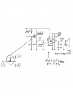
The attached schematic shows my Ruby build. The attached photo shows how I put the 470uF cap across the 9V + and ground. Is this an acceptable way to do it?
Another thing that I noticed is that the hum/noise level is affected by my handling of the volume and gain pots and moving wires around. I don't mean the loud bark such as when my fingers accidentally touch the tip and sleeve of the guitar plug, but rather a much lower level of hum/noise. The level is much lower now with the J113 JFET replacing the stomp box powered by its own wall wart.
To be a little more specific, just now I picked up the gain pot by its wiper shaft, touching no other part of this pot. While my fingers were touching the shaft, I heard a substantial hum/noise, which stopped as soon as I put it down. If I turn the gain pot up, the hum/noise does not go away when I put the pot down.
All this is with the breadboard ground connected to the ground of a wall receptacle. To be clear, the hum/noise problem is better now than it was before. Previously, it was constant; now, only when the gain is on the high end on my guitar or on the Ruby gain pot, or when I am handling a pot or moving things around. My next step will be to put this little amp into a properly grounded metal box.
The attached schematic shows my Ruby build. The attached photo shows how I put the 470uF cap across the 9V + and ground. Is this an acceptable way to do it?
Attachments

Last edited:
Congratulations! 🙂I built the Ruby today and got it working.
Yeah, guitars are a bit more challenging. Even humbucker pickups are somewhat sensitive to electrical interference, and the long cable between guitar and amp doesn't help...With my Les Paul plugged in and all knobs (including both gain knobs) at 10, the sound is dirtier and hum/noise is present.
Good! In the Ruby amp, the JFET is configured as a "source follower", which has unity voltage gain; it doesn't make the input signal any bigger, unlike your stomp box. So hum from the guitar itself won't be amplified, as it would have been with the stomp-box.The level is much lower now with the J113 JFET replacing the stomp box powered by its own wall wart.
It's generally a good idea to have enough gain to get the sound you want, and not much more than that. So if your Ruby has enough gain to let you get to its full output power (and maybe get some overdrive), that's all you need. (If your tastes run to playing metal, you'll need a whole lot more gain, but that's another story entirely.)
Salt water is quite a good electrical conductor; we humans are basically large bags of salt water packaged in skin. So your body - a conductor several feet long - makes a fine radio receiving antenna, picking up the 60 Hz electromagnetic field generated by all the AC wiring in your home. When you touch the pot shaft, you inject this hum signal into the amp.To be a little more specific, just now I picked up the gain pot by its wiper shaft, touching no other part of this pot. While my fingers were touching the shaft, I heard a substantial hum/noise, which stopped as soon as I put it down.
The fix is simple: ground the potentiometer shafts and metal housings! In "classic" tube guitar amps, this is usually done by grounding the metal case of the potentiometer itself. This in turn is done by scraping a small area clean, applying a dab of solder, and then soldering a ground wire onto the metal case.
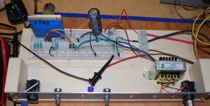
For breadboard lash-ups, I usually use a strip of aluminium flat stock or angle to carry the potentiometers, and ground this metal strip. The pots, being mounted to the metal, are grounded through it. The third pic shows a partially breadboarded tube amp, with both breadboard and aluminium strip mounted to a scrap of pine board. Pots and jacks mount to the Al strip.
This method of grounding-by-contact is NOT reliable for a finished amplifier that will sit around and tarnish for months and years, until there is no longer an electrical contact between pot mounting threads and grounded metal bracket. Which is why old Fender amps have that ground wire soldered to the pot housings.
I think you'll find a huge improvement when you do that.My next step will be to put this little amp into a properly grounded metal box.
For cheap and convenient testing, ye olde dollar store will typically carry metal "cookie sheets" or baking pans for a couple of bucks. Scrape off a small patch of any Teflon coating, use a clip-lead or solder on a wire, and a tray like this makes a handy temporary grounded enclosure (first pic.)
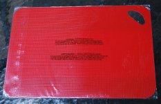
Make sure not to let any other wire ends touch the metal - I usually lay a dollar-store plastic cutting-board or place mat in the bottom of the tray to prevent shorts (second pic.)
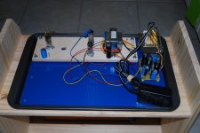
The fourth pic shows a old project (a 2-watt push-pull valve guitar amp) that I built using a dollar store cookie sheet for a chassis, and a dollar store plastic cutting board for an insulating mat. The wooden (pine) structure underneath is an IKEA RAST childrens night-stand, no longer available in Canada. It makes a passable guitar amp cabinet, particularly if you don't have access to a table-saw.
Electrons don't care if you're using a $2 cookie tray, or a $400 polished instrument housing...so I'm happy to use the cookie tray when it fits the project (size, strength, etc.)
-Gnobuddy
Attachments

Generally, you want this cap close to the LM386, rather than close to the battery. However, if the wiring from battery to LM386 is only a few inches long, your present setup should work okay....how I put the 470uF cap across the 9V + and ground. Is this an acceptable way to do it?
The all-important ceramic or film cap - 0.1 uF typically - should be as close as possible to the chips power and ground pins (as I see you've indicated in your schematic.)
The big fat electrolytic filter cap can generally be up to a few inches away from the chip, but closer is better, within reason. If you can get it within an inch or two, great.
In more complex circuits, it's not unusual to have several of these big electrolytic filter caps across the power rails, at several different locations on the PCB.
The reason we want the ceramic or film cap as close to the chip as possible, is that the chip will typically "want" to oscillate at radio frequencies, typically several millions of hertz. At such high frequencies, an inch of wire actually matters - and so we want that cap as close to the chip as possible, to discourage the chip from oscillating.
Electrolytic capacitors are imperfect, and don't work properly at millions of hertz. That's why we need the little ceramic or film cap (for the high frequencies), and the big electrolytic cap (for the audio frequencies.)
Of course it's the audio frequencies we can hear, but remember, the chip wants to oscillate at radio frequencies, and if it does, it won't amplify our audio properly (and will also overheat, interfere with nearby telecommunications, etc.) So we use the belt-and-suspenders approach, the big electrolytic cap, and the small ceramic or film cap.
-Gnobuddy
Electrons don't care if you're using a $2 cookie tray....
Those are very clever adaptations of ordinary items! I'll have to see if I can bookmark that post for when I try something a little more ambitious ... later.
Generally, you want this cap close to the LM386, rather than close to the battery.
I'll remember that when I do the final soldering on the final board.
The all-important ceramic or film cap - 0.1 uF typically - should be as close as possible to the chips power and ground pins....
Right now, the leads of that cap are in the breadboard holes closest to pins 4 and 6. I'll keep them close.
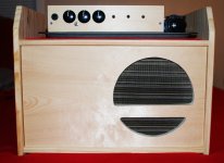
Thanks! One more pic, of a slightly later evolution of the same project. Still a temporary (plywood) front panel, and no housing for the electronics.Those are very clever adaptations of ordinary items!
This ended up as a two-channel, two-watt tube guitar amp, which I used for quite a while, but I always felt that it needed a bit more tweaking on the higher-gain channel, and I never got around to actually doing it. I still have the amp, maybe I'll revisit it some day.
-Gnobuddy
Attachments
The metal enclosure should arrive any day now. I've been thinking that, instead of the gain pot, I may want to use a resistor that sets gain just below the level where the hum/noise appears. One less hole to drill and a cleaner appearance. I know Ohm's Law is relevant here. What is the best way to take the measurements needed to calculate that "threshold" resistance value? Or should I just use a trimpot?
Last edited:
You can test the benefits of a metal enclosure with common kitchen foil, or any convenient metal object of right size (pots, pans, baking trays.)The metal enclosure should arrive any day now.
My vote is for the trimpot. While you can calculate many things, there are also times when a quick tweak on the bench is the fastest and most effective way to get the end result you want.Or should I just use a trimpot?
In this case, the end result is subjective (based on your ears), and will vary depending on the guitar you use, which room of the house you're in, how far you are from the speaker, what sort of bass response the speaker has, the emotional state you're in when you play (hard strums? Gentle finger-picking?), the gauge of strings on the guitar, and so on.
You can't calculate those things, so a quick empirical adjustment is the best solution. Kinda like the spring-loaded tension adjustment pulley that keeps the serpentine-belt or drive belt(s) tensioned on your car engine, regardless of belt stretch, small variations in manufacturing tolerances, et cetera.
-Gnobuddy
Testing the trimpot, it appears that using the LM386 chip to adjust gain results in hum/noise. For simplicity, I'll put nothing between pins 1 and 8 and use the gain knobs on the LP to manage gain.
An unswitched (?) -- open when unplugged --1/4" jack generates substantial noise/hum when the guitar is not plugged in. Replacing the input jack with a closed-circuit version helps a lot.
An unswitched (?) -- open when unplugged --1/4" jack generates substantial noise/hum when the guitar is not plugged in. Replacing the input jack with a closed-circuit version helps a lot.
I suspect what's happening is that you have a lot of hum and noise (because there's no grounded metal enclosure), so *anything* you do to increase gain will amplify the existing hum and noise, making it louder....appears that using the LM386 chip to adjust gain results in hum/noise.
Are you using coaxial cable / shielded cable to connect the input jack? If not, you should be.An unswitched (?) -- open when unplugged --1/4" jack generates substantial noise/hum when the guitar is not plugged in.
If you're unsure what shielded cable is, this is what I'm talking about: Shielded cable - Wikipedia
Also see page 8 of Craig Anderton's book (the first free reference book I linked earlier in the thread.)
Sad to say, these days I usually get my shielded cable by going to the local thrift store, buying a few used RCA to RCA audio cables for a couple of bucks each, and cutting off the RCA plugs from both ends. This is easier and usually cheaper than trying to buy shielded cable from an electronics supplier.
In addition to using shielded cable, wiring to the input of the LM386 (or any audio amp, particularly guitar amps) should be kept as short as practical. This is the most noise-sensitive part of a guitar amp, so we don't want long lengths of wire acting as antennae to pick up noise and feed it into the amplifier.
The several-metre-long cable from guitar to amp - carrying a high impedance, unbalanced, low voltage, signal - is a bit of a disaster in electronics terms. But there is nothing we can do about that now, as guitars are still (electrically) pretty much the same as they were circa 1931, when George Beauchamp created his revolutionary Frying Pan electric guitar with its revolutionary electromagnetic pickup.
It certainly does! And this is pretty standard practice on all guitar amps and guitar FX pedals. The input is shorted to ground when nothing is plugged in, to reduce hum, buzz, and noise pick up.Replacing the input jack with a closed-circuit version helps a lot.
-Gnobuddy
Standard guitar cable into the 1/4” jack. Jack connected to breadboard, vol pot, and ground via standard 22awg wires. With the input jack going to such disparate points, I don’t see how I practically can use a shielded cable. Rather, it seems the best I can do is make the 3 wires as short as possible when I make the final connections.
P.S. 2 wires go to ground; 1 to the vol pot. Still, even if I could use shielded cable, it would be a very short piece.
P.S. 2 wires go to ground; 1 to the vol pot. Still, even if I could use shielded cable, it would be a very short piece.
Last edited:
Of course you can use a shielded cable if you decide to. It's a judgement call for you to make.Still, even if I could use shielded cable, it would be a very short piece.
Right now, by your own account, you have far too much hum and noise. If a grounded metal enclosure calms things down sufficiently, you may be able to get away with unshielded wire from the input jack.
IMO, this is not good practice, though, because the shield not only reduces noise, it also reduces the amps susceptibility to oscillate.
Besides, who wants to build an amp as badly as you can possibly get away with? Perhaps Leo Fender, who was a penny-pinching accountant first, and an electronics tech second. But a DIY builder does it for the love of the thing, usually. We usually want to build well, rather than just barely good enough to be tolerable.
Personally, I always use shielded cable from the input jack, even if it's a three-inch run to the input device. I know from experience that three inches of unshielded wire, connected to a high-impedance guitar amp input, can in fact pick up quite a lot of electromagnetic noise.
You can easily try this for yourself: disconnect the input jack from your JFET gate, and connect a few inches of your 22-gauge wire there to act as an antenna. Try waving your hands, or plugged-in electrical appliances, near it, and listen to what the amp does.
In addition to guitar input jacks, I also always use shielded cable to every pot in a valve guitar amp. Using shielded cable to pots is less important with a 10k pot (like the one you're using) than with a high-impedance 500k or 1Meg pot (typical of tube guitar amps), though. This is because lower impedance points in a circuit are less likely to pick up hum and noise from thin air.
There are two ways to use shielded cable with a pot. One way is to use two separate lengths of cable, one wired between the pot's ground lug and "hot" lug, the other wired between the pot's ground lug and middle lug.
The other way is to buy "stereo" shielded cable, which contains two inner conductors surrounded by a single shared shield that encircles both inner conductors. Ground the shield to the pot's ground lug, wire one conductor to each of the two other pot leads.
The wires are typically colour coded, making it easy to find the right wires at the other end of the cable.
It's true that many amps built on a PCB will not have shielded cable to input jacks or pots. Two things make this possible: a grounded metallic enclosure for the whole amp, and careful PCB layout. A circuit built on solderless breadboard is anything but careful layout, however - breadboards, by their nature, almost force you to have very poor layout.
-Gnobuddy
I guess when I think of shielded cable I think of a multi-wire cable, like a piece of Romex. I’ll try to find shielded single wires.
Even the big electronics distributors don't seem to carry it any longer. I was browsing Digikey's website earlier tonight, and didn't find any bare coaxial cable intended for audio.I’ll try to find shielded single wires.
This is why I've been buying second-hand cables originally intended to connect your bits of Hi-Fi gear together, and cutting off the plugs. I get several feet of wire from each of these cables, particularly since the cables are usually stereo (two wires), while my guitar amps are not.
-Gnobuddy
I found this shielded wire but the gauge is tiny: McMaster-Carr click on “wire.”
There’s also this: https://www.amazon.com/Gavitt-Singl...jbGlja1JlZGlyZWN0JmRvTm90TG9nQ2xpY2s9dHJ1ZQ==
There’s also this: https://www.amazon.com/Gavitt-Singl...jbGlja1JlZGlyZWN0JmRvTm90TG9nQ2xpY2s9dHJ1ZQ==
Last edited:
For our purposes, this is not a factor, because the currents we send down a shielded cable are tiny, usually less than a thousandth of an ampere (and sometimes a thousand times less than that.)...the gauge is tiny...
For example, you have a 10k volume pot, so if your guitar puts out 100 mV (a good strong guitar signal), the current in the pot wires is (0.1V/10,000 ohms), or 0.00001 ampere. I don't think there's a gauge of wire made that is too thin to handle that!
Many of the cables listed on that page are too fat to be good for audio purposes (too stiff, too bulky.) There is one that is listed as 0.11" outer diameter, and that one might work ("Shielded Stranded Wire RG-174/U 50 ohms 26ga 1 0.11" OD Black..."
That one appears to have exposed braid, and no insulator around it.
I've never seen shielded wire like this, and for good reason: if that exposed metal braid touches the metal housing, or any other exposed metal (component leads, etc), bad things can happen, ranging from hum, buzz, pops, and clicks, to outright damage because of a short-circuit.
Who would have imagined that audio coaxial cable would become a rarity?
-Gnobuddy
one that is listed as 0.11" outer diameter, and that one might work ("Shielded Stranded Wire RG-174/U 50 ohms 26ga 1 0.11" OD Black..."
I can work with that one. I was wrong to assume that shielded wire came only as part of big, fat, inflexible cables. McMaster-Carr looks like a good place to mail-order it, but the store in Van Nuys also lists it. Field trip!
- Home
- Live Sound
- Instruments and Amps
- Why does this LM386 breadboard not work as a guitar amp?