HF carry various kinds of solder used for plumbing, etc. These melt at much higher temperature, and will destroy semiconductors and small electronics components immediately, so they're completely unsuitable for electronics construction.I've been using whatever solder I picked up at Harbor Freight.
If you happen to have picked up one of these types of solder, it cannot be used for your current purpose.
I've noticed that, too. Personally, I've never paid attention to the brand-name of solder, only its chemical composition; 60/40, or 63/37.A lot of people on this site seem to like Kester solder.
The latter is my favourite, but I believe 60/40 is easier to learn soldering with, and there is nothing wrong with it at all, so there is no loss in investing in a spool of the stuff.
You're welcome!Thanks for the soldering tips and link.
-Gnobuddy
HF carry various kinds of solder used for plumbing, etc. These melt at much higher temperature, and will destroy semiconductors and small electronics components immediately, so they're completely unsuitable for electronics construction.
-Gnobuddy
It's not the plumbing type. I have some of that left over from copper plumbing projects. It is much thicker and is melted with a gas torch onto red hot metal. No chance I would ever confuse the two. The stuff I picked up is much, much smaller in diameter.
That's a good start. 🙂The stuff I picked up is much, much smaller in diameter.
But we're not out of the woods yet.
The solder you bought - is it bright shiny silver? Or relatively dull silver?
The shiny stuff is lead-free, and much harder to work with. Not recommended at this stage of the game, though I've encountered a couple of experienced DIY builders who used the stuff.
-Gnobuddy
The HF stuff has no specs but is actually duller in appearance than the Kester 60/40. I'm switching over to the Kester.
That might help considerably, if my guess is correct, and you are currently trying to work with lead-free solder.I'm switching over to the Kester.
I suspect this might be the case because this is the only solder for electronics I can find via a search on the Harbor Freight website: Lead-Free Rosin Core Solder
And, as you can see, that particular solder is lead-free. It's not what you need for DIY electronics right now.
One of the reasons why lead-free solder is harder to use at home is that it's much more fussy about temperature. There's very little margin between "It won't melt!" and "It got too hot and made a dry joint!"
This is bad enough when you're working with a temperature-controlled iron, and even worse when you're using a basic iron with no temperature control!
In factory production, lead-free is the norm these days (and is usually required by law.) But they use computer-controlled soldering ovens, with precise control over both temperature and soldering time.
-Gnobuddy
Quote:
Originally Posted by JMFahey
In my book, FIRST get DC voltages right, THEN worry about sound, oscillation or whatever.
It´s an idiom.Please provide a link to your book.
I can do something even better,provide a couple links to its meaning:
in my book (phrase) definition and synonyms | Macmillan Dictionary
IN MY BOOK | meaning in the Cambridge English Dictionary
What does 'In my book' mean? - Idiom Definition - UsingEnglish.com
In any case, I´m actually providing practical advice to solve your problem.
Again:
* FIRST get DC voltages right, THEN worry about sound, oscillation or whatever.
Please do.
Specifically this:
I read 8.26V DC at pin 3 (audio input) of the NTE823 chip and 11.07V DC on pin 5 (audio output to the speaker). So far, for my purposes, so good.
which is certainly caused by:
run the audio in thru a 4.7K 1/2W resistor and a 0.033uF 100V cap to the audio in pin (pin 3)
Nothing will work, nothing else is worth correcting (oscillation, distortion, decoupling, etc.) until you correct this error first.
In a nutshell, I suggest you build the exact datasheet example and try to make it work; mods, experimenting, etc. come later.
Quote: "run the audio in thru a 4.7K 1/2W resistor and a 0.033uF 100V cap to the audio in pin (pin 3)"
Nothing will work, nothing else is worth correcting (oscillation, distortion, decoupling, etc.) until you correct this error first.
In a nutshell, I suggest you build the exact datasheet example and try to make it work; mods, experimenting, etc. come later.
Thank you.
Where did you find that resistor/cap quote? I could not find it in the LM386 or NTE823 datasheets. IAE, I will add those components where indicated. Thanks again.
Last edited:
Gnobuddy, how do you clean components before soldering them? A clean cotton rag (e.g. old T-shirt material) and 70% rubbing alcohol? Of course, I wouldn't want anything moist on anything other than the leads.
That [Kester 60/40] might help considerably, if my guess is correct, and you are currently trying to work with lead-free solder.
Your guess appears correct, If the solder I bought at HF a few weeks ago is the same as they are selling today, then I have been using lead-free. At least it was only a little tube and cheap.
Fahey was quoting from one of your own previous posts, #7:Where did you find that resistor/cap quote?
Fahey's point is that you *do not* want that 4.7k resistor. Also, a 0.033uF capacitor is a bit small for the job (though, in fact, not catastrophically so, given the 50k input impedance at pin 3, and the fact that the amp is for guitar.)...I temporarily removed the pot from the breadboard and now run the audio in thru a 4.7K 1/2W resistor and a 0.033uF 100V cap to the audio in pin (pin 3).
If I understood you correctly, you've changed things a bit since then, and are no longer using that resistor. Dunno if you're still using the same value cap.
-Gnobuddy
Have you read chapter four of Anderton's book yet? All the answers to how to solder are there, right at the start of the chapter, complete with diagrams....how do you clean components before soldering them?
(Cloth and alcohol are not what's needed, but the first few pages of chapter 4 of Anderton's book tell you all you need to know.)
-Gnobuddy
Okay, Thank's for pointing that out. I failed to explain that, IIRC, I put the resistor in there as a temporary substitute for the 10k pot, attempting to emulate a setting of roughly 5 of 10, to eliminate any problems from possible/probable mis-wiring of the pot. My thinking was probably absurd. IAE, I put the pot back in and the resistor and cap are gone. The LM386 datasheet has several schematic examples for different purposes and none has a cap between audio input and pin 3.
Yeah, especially after I moved everything, several wires became disconnected, and I could not figure out where they were supposed to go. When that happened, I pulled out more and reassembled the breadboard along the lines of the circuitbasics.com schematic linked above.
If I understood you correctly, you've changed things a bit since then, and are no longer using that resistor. Dunno if you're still using the same value cap.
Yeah, especially after I moved everything, several wires became disconnected, and I could not figure out where they were supposed to go. When that happened, I pulled out more and reassembled the breadboard along the lines of the circuitbasics.com schematic linked above.
You did mention why you added the resistor. Hopefully, you remember now that a volume control is NOT a variable resistor, but a voltage divider (see post #30.) That being the case, you cannot replace a volume control with a single resistor....IIRC, I put the resistor in there as a temporary substitute for the 10k pot, attempting to emulate a setting of roughly 5 of 10...
Quite true. This works fine as long as the input signal (to the amp) is pure AC, and does not have any DC voltage riding on it.The LM386 datasheet has several schematic examples for different purposes and none has a cap between audio input and pin 3.
A normal electric guitar by itself meets this requirement. So does the guitar pedal you're currently using as a preamp.
There are circumstances when you do want a cap between audio input and pin 3. For now, don't worry about that.
-Gnobuddy
The problem could simply be too little gain. The circuit on page 1 of the thread says 20dB gain. This is small in the world of guitar signals.
Another check would be to plug your guitar into a passive direct box* and connect headphones** where you would usually run a cable to the amp/sound desk and listen for guitar sound.
Additionally find a simple project for an audio oscillator and build it. This should make a tone in your 386 amp. A battery powered oscillator will be useful for all sorts of testing in your guitar and electronic adventures.
Hope this helps.
* or some other high impedance to low impedance transformer.
** Normal nominal 32ohm headphones.
Thanks for your help.Fahey was quoting from one of your own previous posts, #7:
Fahey's point is that you *do not* want that 4.7k resistor. Also, a 0.033uF capacitor is a bit small for the job (though, in fact, not catastrophically so, given the 50k input impedance at pin 3, and the fact that the amp is for guitar.)
If I understood you correctly, you've changed things a bit since then, and are no longer using that resistor. Dunno if you're still using the same value cap.
-Gnobuddy
I am actually more worried about the input cap, which is NOT in the datasheet example and to boot allows >8 Volts on pin 1 😱
And by extension the >11 Volts on speaker out pin
hence my suggestion to build the exact datasheet circuit, PERIOD, no IFs, BUTs or WHYs.
And to feed it what the datasheet example demands, drive what it suggests, etc.
I can´t believe we are running circles with 74 posts, no solution, around a 5 part circuit.
Hey, a PRACTICAL example:
a couple nights ago, late at night, (say 1AM to 3AM) I heard loud voices at my door, my camera showed a couple unsavoury type guys drinking, shouting, sitting on my home doorsteps.
I permanently installed there, long ago and for safety reasons, an Electret microphone, embedded in the wooden door.
Faster than searching my old preamp, I Protoboarded in, what, 5 minutes?, an electret mic driver (a simple 22k resistor connected to +9V) and ... you won´t believe this 🙄 ... an LM386 headphone amp 😱
Fed by a .... 9V battery!!!!!
Of course, it worked on first try, no hum/hiss/oscillation/nothing, just flawless crystal clear reproduction.
And I could listen to whatthey were talking, better than themselves, even though the mic capsule is some 10 meters away and its cable goes through a thick wooden door and then through a thick brick wall, into my workbench.
I used the basic LM386 20X gain and hear anything spoken a few meters around my door, footsteps some 15 meters away (I hear people walking on the street before they appear in my camera field of vision) and if adding the pins1-8 gain boost, I can hear people whispering across the street, go figure.
That´s why I can´t believe your continued "bad luck" building such a simple circuit.
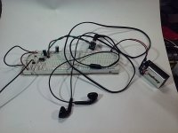
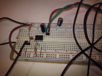
here is the successful "5 minute spy microphone":
Again:
1) build the exact datasheet example
2) once it works, add whatever extras you want to experiment.
3) OF COURSE, feed it 9V to 12V, nothing else.
A fresh 9V battery costs peanuts and always works.
I was in a hurry so decoupling was as basic as can be, just a rail to ground 220uF capacitor, not even a ceramic across the IC, and not even a Zobel at the output, which I would have added if needed, but it worked flawlessly as-is.
A real forgiving little chipamp.
PD: notice I DID refer pin 3 to ground, even if I used a larger than recommended 100k resistor (which I already knew from earlier experiments works flawlessly), did NOT leave it floating as you did, so please correct that mistake before anything else.
No mystery sauce here, my build is as plain vanilla as can be.
Attachments
Last edited:
That´s why I can´t believe your continued "bad luck" building such a simple circuit.
Apparently I've been unclear again. I got it working quite a while ago. Then I messed it up when I was moving everything. Then I got it working again. The current, working version is reflected on the last schematic that I posted, from basiccircuits.com Along this journey, I've experienced hum and other noises. It remains to be seen, when everything is moved to a phenolic board and excess wire is removed, whether the hum/noise will still be there. I'm slow to make the move because I want to make sure I do it in a way that facilitates my longer-term goal - more a woodworking project - of building this little amp and a speaker into the cover of a box that will have a pedal board on one side and the amp & speaker in the lid. ... Although as I think about it, I can always just build the same or a similar amp again if I like the way it turns out. Yeah, I just need to finish this one.
Last edited:
I've never used an LM386 as far as I can remember, but early in this thread I looked up the Texas Instruments datasheet. It includes the internal schematic of the LM386, which is attached here.I am actually more worried about the input cap, which is NOT in the datasheet example and to boot allows >8 Volts on pin 1 😱
Inverting and non-inverting inputs both use a PNP Darlington pair in a slightly unbalanced long-tailed-pair configuration, with a conventional current mirror to combine the outputs and send them on to the voltage amplification stage.
The relevant thing for this particular discussion is that both inputs are biased to ground via internal 50k resistors inside the chip. It looks as though the chip should bias up properly even if coupling capacitors are used to both pin 2 and pin 3.
I assume that the datasheet doesn't show any input coupling cap because this chip was designed for use in low-cost electronics, where the cost of one extra capacitor would be eliminated if at all possible.
I don't know why Jimbo was measuring 8 volts on what he believed to be the input pin - that was clearly a mistake of some sort. My suspicion is that the meter was accidentally measuring the + rail, and not the non-inverting input of the chip.
In fact, looking at the internal schematic of the LM386, even if pin 4 of the LM386 is accidentally NOT grounded, you can't get the full supply voltage at pin 3 - the internal schematic shows you have 30k of resistance plus two Vbe drops between Vcc and pin 3, which is connected to ground via 50k. You cannot get more than maybe 5 volts DC appearing on pin 3 when the chip is powered by 9 V, even with pin 4 accidentally not grounded!
Happily, things have moved on since then, and the 386 is making noises now. 🙂
-Gnobuddy
Attachments
Hopefully, you remember now that a volume control is NOT a variable resistor, but a voltage divider (see post #30.) That being the case, you cannot replace a volume control with a single resistor.
Yes, thank you again for explaining that.
If adding a resistor causes a voltage division, should I EXPECT that to cause a decrease in volume or other signal strength after the voltage division? Inevitably? I ask because the concept of voltage division between a line and a resistor "hanging off the side of the line" was counterintuitive until you provided a link showing a basic voltage division.
Last edited:
Yes! A voltage divider "divides down" a voltage. It makes it smaller. Mathematically, you can divide down the signal to any decimal portion of it's original strength, from 0 all the way up to 1. (But never more than 1.)If adding a resistor causes a voltage division, should I EXPECT that to cause a decrease in volume or other signal strength after the voltage division? Inevitably?
So the volume control in front of your LM386 can divide down the incoming signal all the way to virtually zero, which means the amp becomes silent because there's no signal going into pin 3. When you turn the knob up, you send progressively more and more signal to the LM386.
When you have the right amount of signal coming into the pot, the LM386 will reach its maximum output power a little before the volume pot reaches its maximum position. In your case, you're using your guitar FX pedal to bring up the guitar signal to more or less the right level.
You need a minimum of TWO resistors. A line and a single resistor won't act as a voltage divider.I ask because the concept of voltage division between a line and a resistor "hanging off the side of the line" was counterintuitive
Inside the pot, you have a carbon (or plastic) track that runs between the two end pins. But there is a third pin, connected to the moving wiper that makes contact partway along the track. So you have one resistance from that wiper to each end of the pot; two resistors in total, wired in series, with the wiper at the junction of the two. That's a voltage divider.
An analogy might help. Ever use a long garden hose to water plants? The faucet might be pushing water at, say, 100 PSI into the near end of the hose (this is double what it should be in a real house, but we'll use this number to make the math simple.)
The far end of the hose is open to the atmosphere, which we'll take as our "ground", or zero pressure. So the water pressure at the far end of the hose, right at the opening of the nozzle is zero. (Close enough for our purposes here.)
Let's further suppose the hose is 100 feet long, for convenience.
What happens if there's a slight leak where the hose attaches to the faucet? You see water spurting out under high pressure, right? Clearly there's high pressure at the faucet end of the hose.
What if there is a similar slight leak very near the open end of the hose? At most, you see a little dribble of a leak. Evidently there's very little water pressure there.
Now: what is the water pressure halfway along the hose's length? There's 100 PSI at one end, zero at the other, and clearly, the pressure is falling linearly all along the length of the pipe. So it must be 50 PSI in the middle, correct?
What's the pressure 10 feet from the open end? That's one-tenth of the way along the hose, so it must be one-tenth of the faucet pressure; it must be 10 PSI there.
How about 20 feet from the open end? The same argument tells you you must have 20 PSI there.
And so on, all along the length of the hose. 0 PSI at the open end, 100 PSI at the faucet end, and the pressure in between is proportional to the distance from the open end, 10 PSI for every 10 feet, or 1 PSI for every foot of distance from the open end.
Back to electricity. Suppose you have a 100k resistor instead of 100 feet of hose. Suppose you apply 100 volts to one end instead of 100 PSI. Suppose you ground the other end so it's at zero volts, instead of zero PSI.
Everything works exactly the same way it did with the garden hose: There's 100V at one end, 0V at the other, 50V in the middle. Move 1/10 of the way along the resistor from the zero-volt end, and you'll have 1/10 of the total voltage: 10 volts. Move 1/100 of the way along the resistor from the open end, you'll have one-hundredth of 100V; that's 1 volt.
So if you have a 100k pot, with 100 volts applied to one end, and the other end grounded at 0 volts, do you see what the voltage at the wiper will be as you rotate the pot through its range? Zero when the wiper is at the grounded end; 100 volts at the other end; and somewhere between 0 and 100 when the pot is rotated part-way.
Make sense?
When it comes to electricity, there is a twist to the story: you can have a logarithmic pot. This behaves like a tapered garden hose. Most of the above discussion still applies - 100 PSI at one end, 0 PSI at the other, pressure varying with position in between. But because the pipe is tapered, you won't find 50 PSI halfway along the length - it will be closer to the thin end of the pipe this time.
-Gnobuddy
- Home
- Live Sound
- Instruments and Amps
- Why does this LM386 breadboard not work as a guitar amp?