Being a fan of point-to-point 👍
Nigel, you're good on all accounts, and I'm happy to read that you did use your common sense for plenty of positions
heatsinks - just trust in your fingers - if you can keep finger on sinkls for 10sec, critters are happy; if shorter time, increase sinks to keep critters happy
regs - in principle - decent sch is 50%; next 50% is layout of traces - not just GND for all elements, but also differentiating power traces from sense traces etc.
for PtP, you're most likely fine
edit: I did wrote several times - some of my lousy attempts to explain some details of xformer woodoo ...... and frankly - lazy tonight to search or write again
re-read what I wrote today, take in account that usually xformer with lower nominal impedance is having lower Inductance of winding, thus demanding lower drive/generator output impedance
simple as that
our usual JFet buffers are - as confirmed, good to drive nominal 150R (reaching low freq.) but lower than that, bass would suffer .........
Thanks, Ben. I enjoy doing p2p, although I sometimes worry (perhaps needlessly) about whether the end results are as good as a PCB would be.
ZM: Thanks for all the feedback. I'll keep pondering the transformer "woodoo", and your other comments. Meanwhile, the little heatsinks are definitely too hot; 2 or 3 seconds max. Not a big problem to replace with bigger heatsinks, though.
Hi Mighty ZM,
can I use a Good Gemini Shunt to feed a channel of Pearl 2 ?
Which phono could you recommand ?
can I use a Good Gemini Shunt to feed a channel of Pearl 2 ?
Which phono could you recommand ?
yes, you can
just help me to help you (regarding programmed current in shunt) - what is current consumption of Pearl 2 and rails voltages ?
lazy to check by myself
Phono - have no recommendation - you already know what's popular in Papaland
ha!
I know - make M2 !

just help me to help you (regarding programmed current in shunt) - what is current consumption of Pearl 2 and rails voltages ?
lazy to check by myself
Phono - have no recommendation - you already know what's popular in Papaland
ha!
I know - make M2 !
Thanks.
Rail Voltage is +/- 24Vdc and 100mA...
I already have a BA3, a Vfet lotery Pt2 and yes, M2 will be the next (and a AB100 for summer...😉)
Rail Voltage is +/- 24Vdc and 100mA...
I already have a BA3, a Vfet lotery Pt2 and yes, M2 will be the next (and a AB100 for summer...😉)
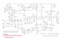
for search engine: Pearl 2 current consumption
ok, see enclosed
actual current consumption is in range of 50mA per channel, taking in account highish Idss specimens of 2SK170BL (correct me if I'm wrong there)
now, I need to know 2 things:
- dual mono regs or one common for both channels?
-which exact schematic of Good Gemini you're counting on?
ok, see enclosed
actual current consumption is in range of 50mA per channel, taking in account highish Idss specimens of 2SK170BL (correct me if I'm wrong there)
now, I need to know 2 things:
- dual mono regs or one common for both channels?
-which exact schematic of Good Gemini you're counting on?
Attachments
Hi ZM,
Have you released the Good Gemini Shunt psu as a stand-alone project with pcb files? This would be nice to have in one’s DIY toolbox.
Have you released the Good Gemini Shunt psu as a stand-alone project with pcb files? This would be nice to have in one’s DIY toolbox.
well, I didn't even think of it .......
can send these to Jim, as supplement to Iron Pre
though, that way you'll see them in Store in a year or two
not complaining in any way - I'm completely aware that Store isn't a day job for our Boyz
can send these to Jim, as supplement to Iron Pre
though, that way you'll see them in Store in a year or two
not complaining in any way - I'm completely aware that Store isn't a day job for our Boyz
I don't know yet if I go for dual mono or not ... schematic for Good Gemini will be the one used in the Iron Pre... or maybe there is a general rule to obtain desired voltage and current so that I could make a PCB and release the gerber files when it's done🙂
Damien
Damien
for mono feed, let's say that programmed current could be 100mA
for both channels, let's say that programmed current could be 160mA, but 200mA even better
now, if you're able to set that, and also change few resistor values to get proper span of output voltage within pot travel, you're probably capable of making decent reg pcb
if you aren't, invest some in more Porridge (good for brain) and some elbow grease ...........
🙂
I'm here to help with any dilemma .........


I've been fiddling with the p2p Good Gemini. I tried larger heatsinks on the BD139 and MJE350, which gave enough time to find that the mosfets were getting really hot. (Infrared doodad said around 100 celsius...) So I turned it all off, and looked for the mistake... Turns out I'd misconnected the parallel 15R resistors, which (I think) meant that far too much current was passed by the CCS (? Did I get that right ? ) so I took things apart and rebuilt with things connected correctly. (Always much more difficult than getting it right the first time...)
Things are now working correctly, I think, and the heatsinks I was using before now seem adequate for the big bjts. However I think the mosfets are still getting too hot (although nowhere near as bad as before). Is there any reason to think this is because of the substitution I made of IRF 530/9530 instead of IRF 510/9510? If it's normal for the 530/9530 it isn't a big problem just to put small heatsinks on them, but it might be a sign there's something else wrong, I guess...
Any thoughts?
current through these is simple : programmed current - current through load
dissipation is said current * voltage
so, if you have 0V65 across programming resistors, calculator is giving you confirmation of programmed current
you don't need sinks on mosfets up to 500mW or so ...... in fact even more up to 750mW
so, use your brain and calculator and that's it
if in doubt that they're too hot, put sinks
write here what are you shooting at - output voltage, programmed current, load current
I don't know what you're building and in what arrangement (to be fed with Good Gemini)
Thanks ZM. Since you asked, my aim here is to build the reg close to as originally designed; transformer with dual 15VAC secondaries, looking for 15VDC output to play with p2p SE Iron Pre and experiment with ebay transformers. (Some already here, some on the way... ) So target currents are the same as the ones you discussed above. The only variations are due to using what I had in my junk box, rather than buying new parts, so there are a fair number of substitutions. Mostly pretty close ones, as I discussed above. In particular, I'm using paralleled 15R to give 7.5R on R3/4 and R5/6, so current should be as previously advertised.
Anyway, I checked everything over again, and I have 0.676 V across R3/4 and R5/6 (these are what you call the prgramming resistors, right? Because they set the current?) which close enough to the 0.65V you mentioned. So all is well there. And as you say, this should leave the heat to be dissipated at about 1/2 W, or a little more. Nonetheless the mosfets still got hot; after a couple of minutes they were already over 60 degrees C, which is just about in the safe zone for the usual discussion of heatsinks and Class A amps, so I guess would be OK here (as you said above) but it left me uncomfortable...
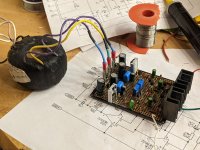
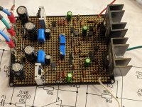
So the junk box came to my aid again; in the photos you can see I turned the mosfets around and put heatsinks on them. Actually I got lazy and sacrificed the old mosfets; the new ones are IRF 630/9630. Now the heatsinks get warm to the touch, but no more than that. Same for the small ones on the BD139/MJE350. All seems to work well; I have +/-15.00V on the rails.
So now on to p2p amp boards! My plan is to build them in such a way that I can easily switch different transformers in and out, perhaps on daughter boards, somehow, and see what sounds good. Should be fun.
Which brings me to another question. One of the two Jensen JT-11-HFMPC that I bought was faulty (open circuit on the secondary. Or maybe the primary; I'd have to check to be sure). The seller was good about replacing it with no bother, but he didn't want the faulty one back; told me to ditch it. Seems a shame, though; so I wondered: Is there anything I could do with it? I don't see any way to fix it, and since its bifilar I don't think you could salvage one winding while removing the other, but is there anything clever I could try with the core if I removed both windings? Or any other ideas? It's 80% nickel, so it seems a shame to just throw it in the trash...
Thanks again for all the help!
Best
Nigel
Anyway, I checked everything over again, and I have 0.676 V across R3/4 and R5/6 (these are what you call the prgramming resistors, right? Because they set the current?) which close enough to the 0.65V you mentioned. So all is well there. And as you say, this should leave the heat to be dissipated at about 1/2 W, or a little more. Nonetheless the mosfets still got hot; after a couple of minutes they were already over 60 degrees C, which is just about in the safe zone for the usual discussion of heatsinks and Class A amps, so I guess would be OK here (as you said above) but it left me uncomfortable...
So the junk box came to my aid again; in the photos you can see I turned the mosfets around and put heatsinks on them. Actually I got lazy and sacrificed the old mosfets; the new ones are IRF 630/9630. Now the heatsinks get warm to the touch, but no more than that. Same for the small ones on the BD139/MJE350. All seems to work well; I have +/-15.00V on the rails.
So now on to p2p amp boards! My plan is to build them in such a way that I can easily switch different transformers in and out, perhaps on daughter boards, somehow, and see what sounds good. Should be fun.
Which brings me to another question. One of the two Jensen JT-11-HFMPC that I bought was faulty (open circuit on the secondary. Or maybe the primary; I'd have to check to be sure). The seller was good about replacing it with no bother, but he didn't want the faulty one back; told me to ditch it. Seems a shame, though; so I wondered: Is there anything I could do with it? I don't see any way to fix it, and since its bifilar I don't think you could salvage one winding while removing the other, but is there anything clever I could try with the core if I removed both windings? Or any other ideas? It's 80% nickel, so it seems a shame to just throw it in the trash...
Thanks again for all the help!
Best
Nigel
Attachments
xformer - if you can't actually see broken wire somewhere close to soldering pins, then play some surgery soldering escapades, little you can do with it
rest - looking good
ditch those horror connectors, when you're done with xperimenting
rest - looking good
ditch those horror connectors, when you're done with xperimenting
xformer - if you can't actually see broken wire somewhere close to soldering pins, then play some surgery soldering escapades, little you can do with it
That's too bad...
rest - looking good
ditch those horror connectors, when you're done with xperimenting
You don't like the spade connectors between the transformer and the board? Or you mean the temporary wires on the output? (They'll certainly be replaced by something better.)
So you would usually solder the secondaries of transformers to the boards? Same with your amp builds?
I used these spade connectors this time since I used them on prasi's M2 boards, and liked them better than the screw connectors I've used in the past. No reason why things can't be soldered when all is done, though, I guess.
I used these spade connectors this time since I used them on prasi's M2 boards, and liked them better than the screw connectors I've used in the past. No reason why things can't be soldered when all is done, though, I guess.
Wow,What's wrong with the kiss,boy ? ........ or - How I gained a gain ,little before Lee De Forest and little after Papa
lookie : Iron Pre | Zen Mod Blog
I already posted that link in few places here , but as it seems ,few Greedy Boyz are greedy for more info
cheap and clean way of having 6db (or little more ,with different gain device)
it's already everything written in that blog post , but to recapitulate :
-pot , then buffer of your choice , then 600:600 xformer connected as autoformer , voila! -there is 6db gain
if approach was good eons ago , when microfarrads and active gain devices were much more expensive than chunk of copper and iron,if approach is good for numerous mic input stages , if approach is good for F6 and especially M2 (buffer-autoformer-buffer) , it must be god for line stage too.
and yes , with 1+1 autoformer , Rout is four times Rout of buffer itself
xformers : Edcor have few , Jensen , Sowter, Lundahl etc.............
-do not expect that more expensive ones are necessary better sounding,
-do not expect maximum verity from buffer if you not use decent (shunt , my poison) reg.
-you can go wild and make your own autoformer , equipped with 24 taps , so skip pot on input and use autoformer at output, as volume attenuator and gain device ,as one device
-or you can make it this way - buffer -commercial AVC (200$ Slagle?)-output autoformer
-or you can go wild and connect commercial AVC to appropriate tap , as output autoformer and have 6db gain ...... that would be buffer -commercial AVC connected on proper tap
now I'm working on balanced Iron Pre ..... will post that soon too
edit on 11.10.2020. : last files for SE and Bal iteration are in posts #1149 and #1150
I’ll just say it, you are ******* amazing. Your Iron Pre is just beautiful. And how could anyone not be astonished at seeing how detailed an enclosure that is. I’m on the floor!
And it’s only 9 am haha
Witty in spades. Well done Zen!
Top of the morning to ya
- Home
- Amplifiers
- Pass Labs
- What's wrong with the kiss, boy?