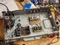
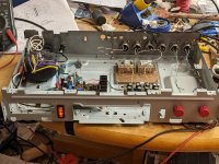
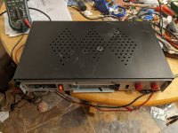
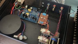
Here are some photos of my first experiment. I'm listening to it right now, and it sounds great! Connected to my diy M2s and B&W CDM2 bookshelf speakers.
I continued with the "garbage and leftovers" theme, and did almost everything using parts salvaged from old projects and spares left over when other things were finished. Nice to use up some of these up. The case is an old CD player (I think) that I started making into a pumpkin preamp years ago when I lived in Brazil; the XLRs were fitted back then. Project was abandoned long ago and the case has been kicking around ever since. Volume pots are quite nice little NOS clarostats (I think) I got from ebay some time back, but nothing special and not going to stay in a "final" version. (I really like the vintage red knobs, though...)
The main buffer board is also p2p, but the bottom isn't quite as pretty as the PSU one. Jfets are from my (very small) stash of original toshibas, and I was lucky to get very close idss matches. I put them in little sockets, so that if I don't want to keep them in this then there's no potential damage from unsoldering them.
As I think I said earlier, my plan is to substitute different transformers if and when I can find interesting things to try out, following ZMs comments on telephone repeaters and similar, back up near the top of the thread. I also want to measure some stuff with REW.
A couple of questions. How much do you need to be concerned about the DC offset? I realise the point is not to get DC across the transformers (just as you don't want it across tweeters in a DC coupled power amp). But once you get it down to 1mV or less then is there any reason to fight to get it better? Seems to me that the heat being put into a transformer with a 250R primary (which is about what these are) is tiny; only V2/R = (0.001)^2/250 = 4 x 10^(-9) watts. On the other hand those wires in the transformer are really small also. I couldn't find any max value on the datasheet for this, but perhaps I don't know what to look for.
As a related question, how accurate are DMMs in measuring values below 1mV?
Nigel
Attachments
1mV figure is OK
DMM is precise there, though depends of quality of same
if it's POS, better toss it through window ...... lousy DMM is worse than none
if it's not POS, good
DMM is precise there, though depends of quality of same
if it's POS, better toss it through window ...... lousy DMM is worse than none
if it's not POS, good
Thanks. I'm curious though. Although it's helpful to know that 1mV is OK (which seemed likely, as I said above), I'd still like to understand how you can tell what is OK and what is not. Here's the datasheet for the Jensens I'm using:1mV figure is OK
DMM is precise there, though depends of quality of same
if it's POS, better toss it through window ...... lousy DMM is worse than none
if it's not POS, good
https://www.jensen-transformers.com/wp-content/uploads/2014/08/jt-11-hfmpc.pdf
All I can see is that signals should be "free of DC", which seems a little imprecise. Did I miss something? How can you tell? At least at low offset levels I presume the issue is the heat generated?
simple logic
signal xformers were and are used in all sorts of circuits (DC coupled) , from dawn of electronic era
in many cases, TempCo (DC offset in time/temperature domain) of used circuits was much worse than you have with your buffer
so , even if I'm setting mine under 1mV, you're good with 1mV, if you can't bring it lower
that's all matter of preventing DC flux in core, Rdc of winding there being just factor
so, just chill and ....... chill
Thanks. Makes sense. In the end I got mine down lower; somewhere around 0.1mV. The rails are showing +/-15.00 V, so all seems in order. Sounds good, too!simple logic
signal xformers were and are used in all sorts of circuits (DC coupled) , from dawn of electronic era
in many cases, TempCo (DC offset in time/temperature domain) of used circuits was much worse than you have with your buffer
so , even if I'm setting mine under 1mV, you're good with 1mV, if you can't bring it lower
that's all matter of preventing DC flux in core, Rdc of winding there being just factor
so, just chill and ....... chill
No surprises there, of course. I never doubted it would... 😎really?

I'm going to be interested to see whether I like it better than the BA-3 preamp, which I've really been enjoying with the M2 recently.
I played around a bit in REW to measure my garbage-can Iron Pre and compare with he BA-3 I made recently. I don't pretend to have a very good idea of what I'm doing in REW, but I found it interesting to compare the two. (I could have saved the files better, perhaps, but I didn't realize how bad they looked until I had the Iron Pre back playing music, and I'm not inclined to turn it off...)
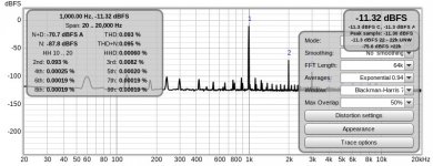
I used a 47k load resistor. For both of them I set the preamp at maximum volume and controlled the volume on the Focusrite that provided the 1kHz signal. (And produced the data, of course.) The idea was to eliminate the quality of the volume pots from the comparison, hence the choice of -11.3 dB, since that was the quietest I could get the BA3 at full volume.
As I reported elsewhere, the PSU in the BA3 is pretty simple, and really wasn't intended to stay in there. Probably the source of most of the extra noise, rather than the preamp board, I'd guess. Interesting that all the even multiples of 60Hz turn up on the BA-3, but not on the Iron Pre. And of course, the H2 and H3 levels are much higher on the BA3, but that's widely discussed elsewhere. I had previously fiddled around with P3 using REW, so I haven't tried to get the absolutely best THD; I just tweaked the H2/H3 balance a bit.
One minor frustration is that the transformer on the Iron Pre is humming a little; I mean a mechanical hum when power is on, not a hum in the speakers. It isn't a big deal since it isn't audible when playing music, but it is something I should sort out if/when this goes into a better chassis.
Attachments

someone else, having experience with REW, should chime in
you don't need to have that weed between 1K and harmonics
also, when doing sshot, harmonics (2K,3K,4K etc.) need to be visible
you don't need to have that weed between 1K and harmonics
also, when doing sshot, harmonics (2K,3K,4K etc.) need to be visible
The "weed" as you put, between 1k and the harmonics, may be due to my inexperience with REW. I'm working on it.
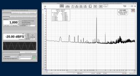
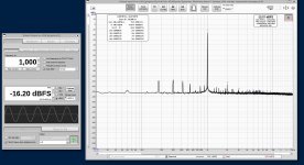
You're definitely right about the poor quality of the attachments (sorry 'bout that), so I've repeated the exercise. Here are screenshots, showing the relevant info. The BA3 preamp clearly has worse performance, certainly due to having a much simpler PSU. It was never intended for actual use, I just threw it together to see what would happen. Turned out to sound better than I expected. (And much better than it measures, IMHO.) I don't know what's going on with the hash around 6k - 7k. It's not audible in use.
I ran the same thing on the Iron Pre twice, changing the settings to either have the same input, or the same 0.707V on the output, due to different gain. I wasn't sure which was the fairer comparison, although in the end I don't think it matters much. The peaks at 180Hz, 300Hz... may be a result of my ignorance and misuse (malpractice?) in REW. But even with those limitations you can see how the BA3 has the H2 thing happening, and that the Iron Pre does not.
Next step is to find out whether the PSU in the Iron Pre is producing more junk than it should, or whether I'm doing something wrong in REW.
Attachments

just persevere with REW, reason is most likely there
I can't help, practically never had it installed
what you're getting with simple loop measurement - soundcard out directly to soundcard input?
I can't help, practically never had it installed
what you're getting with simple loop measurement - soundcard out directly to soundcard input?
Yes, although it's a Focusrite Solo, so it's supposed to be quite good for this sort of thing. xrk971 has threads discussing this stuff, and I've been trying to follow those.just persevere with REW, reason is most likely there
I can't help, practically never had it installed
what you're getting with simple loop measurement - soundcard out directly to soundcard input?


RE: Standalone Gemini
I had built one of the older Iron Pre boards awhile back. In between swapping iron and bridging traces I made a bit of a mess with the board. I ended up chopping the Iron section off and just using the reg. Works like a charm! In this pic its powering a common drain follower, allowing me to ditch the coupling caps (think DCB1) and run straight to the Slegle autoformer. Probably the best sounding line level gear I own.
Now here's my question for ZM – do you imagine substituting an Iron Turtle into this setup would improve things further, or is the magic really in the entire Pumpkin package?
Attachments
well, you already know that entire package now is on big MoBo, so wiring is really minimized, regarding all inputs, all outputs, lines between buffers and Turtle too
all in all , much neater and most likely better for sound ..... if not sound per se, then possibility of stray interference is smaller ...... that resulting in deeper background
and now - more important thing - simple Toshiba same-sex JFet buffer and even simple complementary JFet buffer - can't compete with 3+3 pcs of 2SK2145BL in same-sex buffer topology
these (simple ones) are, current wise, in one Idss range, while "my" buffer is set to 20mA ....... and xconductance is even more upped that ratio of Iq
can you hear that difference, that's another matter
I can hear it, and it was measured
is it important as sum you need to pay for ...... well - just do what's more fun for you, that needs to be most important criteria
Yours is most certainly the penultimate buffer in my book. I may try that out on this perf board version – I think I can scrape together enough for a 2+2 same sex match. Not exactly right thread for this, but did you update Pumpkin buffer to be 3+3 same sex?
- Home
- Amplifiers
- Pass Labs
- What's wrong with the kiss, boy?