you can't easily find happier camper than, say, my Bubba Bob - he's enjoying in Iron Pumpkin - SissySIT combo - first ending with Iron, second (sorta) starting with Iron
when implemented properly**, it's hard to beat stage with decent xformer; anything else is presenting greater level of signal conditioning
**as with everything - not general rule; there is no part which can cover all possible needs and scenarios
when implemented properly**, it's hard to beat stage with decent xformer; anything else is presenting greater level of signal conditioning
**as with everything - not general rule; there is no part which can cover all possible needs and scenarios
What is the total current drawing (shunt reg and buffer) ?
post #1149
for positive rail I=Ube/(R3//R4)=0V65/7R5=87mA
for negative rail I=Ube/(R5//R6)=0V65/7R5=87mA
CCS up and CCS down are defining sum current draw
buffers are pulling, say, 8mA per channel, sum is 16mA, so rest to 87 is wasted in shunt mosfets on end of reg
programmed current can be lowered to, say, 50mA without penalty
for that said resistors need to be 0V65/50mA = 13R (sum of two, so 27R is nice value for all of them)
yes, input relays, pre-reg feed points, in case of 24Vdc relays, one pulling under 10mA
Last edited:

I miss few parts but almost done 
Can we use the autoformer output config with any preamp to swith between no more gain, +6dB or +12dB ?
Damien
Can we use the autoformer output config with any preamp to swith between no more gain, +6dB or +12dB ?
Damien
I want to put some after Wayne Linestage to drive my BA3 output instead of its original front end.
Thanks Mighty ZM
Thanks Mighty ZM


My ebay habit may have got the better of me again. I bought a pair of Jensen JT-11-HFMPC at what looked like a good price, with a vague idea of trying a point-to-point Iron Pre. They haven't arrived yet, but now I'm wondering whether they're going to be appropriate or not. Not the end of the world if not (I can just keep them for some other future project) but I thought I'd ask what people think.
The datasheet (at https://www.jensen-transformers.com/wp-content/uploads/2014/08/jt-11-hfmpc.pdf) shows an input impedance of 1.07k, and output impedance of 600R. If I understand the thread correctly (no guarantee of that) then the recommended transformers are all 600:600. On the other hand wouldn't it be possible to connect these up as autoformers just the same? The gain would be different (lower; looks to me to be 3-4 dB, which is fine as far as it goes) but would they work well otherwise?
As a follow-up question, is there any reason why you can't turn them around and use the secondary as primary (and vice versa)? Looks to me like that would give a gain of 8dB or so, but there's no such thing as a free lunch, they say, so i suspect I've missed something. One possible issue might be the DC resistance, which is higher than the JT-123-FLPCH at 310R on the secondary (and 240R on the primary).
Thanks for any input!
Nigel
what is important from linked datasheet:
Line Output Transformer
1:1 BIFILAR WINDINGS....
....
This transformer is designed for high performance 600 Ω output stages.
Specially processed 80% nickel alloy core material is used for lowest possible harmonic distortion of low frequency signals. For optimum performance, driving signals should be free of DC and source impedance should
be 50 Ω
so you're good
now - there are no center taps on primary, nor secondary, so you'll end up with 6db of gain.......... 12db not possible without center tap
simple as :
pin 3 - GND
Pin 1 and pin 4 tied together - there goes input from your buffer
pin 2 - that's your output
it'll sing, no worries
what is important from linked datasheet:
Line Output Transformer
1:1 BIFILAR WINDINGS....
....
This transformer is designed for high performance 600 Ω output stages.
Specially processed 80% nickel alloy core material is used for lowest possible harmonic distortion of low frequency signals. For optimum performance, driving signals should be free of DC and source impedance should
be 50 Ω
so you're good
now - there are no center taps on primary, nor secondary, so you'll end up with 6db of gain.......... 12db not possible without center tap
simple as :
pin 3 - GND
Pin 1 and pin 4 tied together - there goes input from your buffer
pin 2 - that's your output
it'll sing, no worries
Awesome, that's good news! Thanks for the quick response, ZM.
6db of gain is fine by me. I had already guessed that with no center taps I wouldn't have the flexibility that the intended transformers have. But out of curiosity, what difference would the different impedances and/or DC resistances make? (When compared to the JT-123-FLPCH, say.) And if not when used here, then would they in other situations?
Thanks again!
Nigel
don' bother with these details too much
as I cited up, bifilar means that primary and secondary are wound together, 1:1 means that they're having same number of turns
difference in Rdc is because of tinier wire in secondary
in this circuit - they'll work and those tiny details aren't of special importance , simply because you're not going to drive heavy loads ...... 10K being most likely lowest Rin of amp they'll ever see
even Iron Pumpkin, with designed Rdc of 100R for entire winding, isn't exactly made to drive heavy load, but some of Boyz being lucky enough to have it - informed me that IP is damn good headphone amp, as is; go figure
so, again, you're good
A Happy New Year to one and all!
I'm spending some time over the holiday soldering up the p2p iron pre, although at present I'm doing the power supply, since when the Jensens arrived one of the them was faulty and needs to be replaced. (Seller is being good about it, just a delay. These things happen.) If my soldering looks nice enough to show maybe I'll post pictures later.
Meanwhile I have a question. ZM: you have made the point that it is worth trying different things out, which appeals to me, but what makes a transformer a good candidate to try? For instance, the Lundahl LL 1575 (which is presently available cheaply on a well-known internet site) is also 1:1 bifilar, like the ones above, but is really designed for a different purpose; it's a video transformer, with a much higher bandwidth than needed, and intended for 75R not 600R. It also has a much lower DC resistance (4.5R on each of primary and secondary) than the others we're talking about, and a primary impedance of at least 3.5k, which is also different. Which of these things matter, and which don't? Here's a link to the datasheet.
https://www.lundahltransformers.com/wp-content/uploads/datasheets/1575.pdf
I'm likely not going to buy these anyway (although the price is certainly reasonable), I'd just like to understand a little better. Thanks for any input.
Rdc - lower is better, meaning lower losses in xformer itself
main characteristic - declared nominal impedance - simply put - it shows what;s inductance of windings, defines lower F3 and gives info how hard source need to work
take as example regular Cinemag repeater - having 150R+150R in primary, same in secondary
nominally 600:600R
we are using these in amps, feeding 150R tap, stacking rest of them, thus ending with gain of 4V/V, 12db
so, single Toshiba complementary buffer is able to drive nominal 150R winding, and take that as lowest practical value
but, 75R is task too heavy, even for my wakoo triple Toshiba JFet follower
Hi ZM, thanks for the explanation. Hopefully all this will slowly fliter through and I will understand better. To summarize, the issue is not the transformer (which is 1:1 and would indeed provide the gain we're looking for) but that the buffer before it (or anything similar) can't drive it. Right?
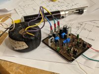
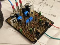
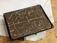
On a related topic, here are some photos of the p2p Gemini shunt reg I finished this evening. I decided to limit myself to only parts I already had lying around, as extras from old projects, or ones I could pull off boards that are no longer in use; the idea being to use up some of the things that I have kept "in case they were ever useful", and not buy anything new. Mostly worked out well. The transformer is a Holden and Fisher 30VA, with dual 15V outputs, which is one of a pair I bought on ebay a while ago, for a project I ended up not building. Some of the resistors are made up from pairs in series (since I lacked the exact values) and in some cases are only approximate. I figured that within 5% or so is probably fine, since if closer tolerances were needed ZM would surely have said so. (Although perhaps he did and I missed it...) Slightly more seriously, I didn't have the right mosfets, so I used IRF 530 and 9530 instead. Does it make any significant difference? My guess is no. And finally, I had several BD139 I could pull off old projects, but no BD140, and several MJE350, but no MJE 340; so I mixed and matched, using one BD139 and one MJE350. Since the schematic looks like two single-rail PSUs, one on top of the other, it seems to me it proably doesn;t make any difference.
Anyway it worked first time - which is always nice - and I'm quite pleased with the p2p wiring, which looks a lot cleaner than mine usually does although I still need to clean the flux off and tidy up a little.
The only concern is that the heatsinks seem too small for the BD139 and MJE350. Before I go any further I think I need to root around in the junk box and find ones slightly larger.
Best
Nigel
Attachments

Nigel, you're good on all accounts, and I'm happy to read that you did use your common sense for plenty of positions
heatsinks - just trust in your fingers - if you can keep finger on sinkls for 10sec, critters are happy; if shorter time, increase sinks to keep critters happy
regs - in principle - decent sch is 50%; next 50% is layout of traces - not just GND for all elements, but also differentiating power traces from sense traces etc.
for PtP, you're most likely fine
edit: I did wrote several times - some of my lousy attempts to explain some details of xformer woodoo ...... and frankly - lazy tonight to search or write again
re-read what I wrote today, take in account that usually xformer with lower nominal impedance is having lower Inductance of winding, thus demanding lower drive/generator output impedance
simple as that
our usual JFet buffers are - as confirmed, good to drive nominal 150R (reaching low freq.) but lower than that, bass would suffer .........
Last edited:
- Home
- Amplifiers
- Pass Labs
- What's wrong with the kiss, boy?