20R (T93YA20R)
I will give the above suggestions a go later tonight. Thank you codyt and Zen Mod.
I will give the above suggestions a go later tonight. Thank you codyt and Zen Mod.
Ok, so bypassing the gain stage brought the low end back in.
Furthermore, the gain was about the same bypassed or jumped in the normal 6 or 12 db configuration. I cant imagine I have two bunk jensons, I must have something wrong here.
Furthermore, the gain was about the same bypassed or jumped in the normal 6 or 12 db configuration. I cant imagine I have two bunk jensons, I must have something wrong here.
Last edited:
remove jumpers
measure Rdc :
between out and gnd
jumper pin 1 and gnd
jumper pin 3 and gnd
mid pin is pin2
Jensens came easily in pcb?
I mean - you didn't rotate them for 180deg ......... ?
pin 1 is closer to out pads, both channels
measure Rdc :
between out and gnd
jumper pin 1 and gnd
jumper pin 3 and gnd
mid pin is pin2
Jensens came easily in pcb?
I mean - you didn't rotate them for 180deg ......... ?
pin 1 is closer to out pads, both channels
Last edited:
Right:
pin1 28.9R
pin3 58.2R
between out and gnd OL
Left:
pin1 28.9R
pin3 58.2R
between out and gnd OL
Jensens went in without a hammer and the pins will not allow them to be rotated 180
I got the boards at the beginning of September (about a month ago) from ItsAllInMyHead, but I have no clue when they were made. I would guess that several other successful projects have been made on the same run of boards.
pin1 28.9R
pin3 58.2R
between out and gnd OL
Left:
pin1 28.9R
pin3 58.2R
between out and gnd OL
Jensens went in without a hammer and the pins will not allow them to be rotated 180
I got the boards at the beginning of September (about a month ago) from ItsAllInMyHead, but I have no clue when they were made. I would guess that several other successful projects have been made on the same run of boards.
well, I believe you can do that from above - check do you have continuity between Jensen pins 1 and 8
if not, solder tiny wire bridge between them (best to do it from bottom side, so you need to unbolt pcb)
I knew that - ( I wrote few times about mishap I had) when I lost consistency between brd and sch file that I will be in trouble ....... and trouble persist
keep me/us informed
edit: Ha! now I remember - blame Pa, as always !!
Last edited:
The "issues" that I can remember that were corrected from boards marked Iron Pre Zen Mod 2018 with latest batch of boards were/are:
Pin-out for transformers: Check all against schematic / spec sheet. Think Jensen / Cinemag may have needed some doctoring. Think Edcor was okay.
Ground trace for outputs - May not be required, but some people had some hum. Cut a few traces.
iifnotany - Did I send you boards marked 2018 or 2020? I think I only had 1, 2018 board left, but can't be sure. Hope it's all up, running, and sounding fantastic soon. Definitely worth the effort.
well, if what I wrote above is cure (pin 1 and 8 missing connection) ........ and 99% I'm sure it is, just another confirmation of ZM's Omniookness

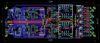
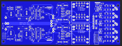
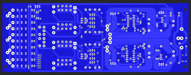
it seems that I'm going to Berserk and draw new pcbs from scratch ........ this time having proper consistency between brd and sch files
doing it this way is sorta old time - back of napkin for both schm and board ........ but main problem is, besides doing it old way, I didn't had any pcb on my bench ..... I mean - schm as whole was proven not once in various iteration, but this pcb wasn't
Last edited:
We get to build a killer pre-amp and learn a bit about debugging along with schematic / PCB tracing validation along the way. I learned more on this project than most. It's an honor to work on the early iterations and help out, not a burden.

Its all good now!
That was it. I read about the trace issues further back in the thread, but for some reason thought is was only the Edcore pins the were affected.
@ItsAllInMyHead - It was a 2020 board and I can not agree more that this was a very good learning experience. Also thank you for the board!
And thanks again Zen Mod for all the time you put into this and the time you pit into helping me.
Can you detail what exactly you ended up doing? I should check mine and make sure its correct.
Just a small 26 awg jumper wire soldered between pins 1 - 8 on each transformer. its a bit ugly but on the underside of the board. I'll add a picture later toady.
Woo Hoo!
iifnotany - Thank YOU! Clearly my notes were wrong. I thought that issue was corrected between the "2018" iteration and the "2020" iterations I had made. I think the latest batch that 6L6 was having made have that issue corrected in the PCB layout. ZM / 6L6 will need to confirm with current boards and revision notes.
Enjoy the tunes!
 Now it's time for Music!
ZM - Note that this holds true for the Bal 2020 boards too. Just checked my notes, builds, and actual unused boards. I'm not sure who else has built balanced.
Please verify below.
In situ - incorrect measurement from Pin 1 to Pin 8 of Jensen is ~112R / 115R.
Correct is 0R.
Below are relevant snips from schematics.
SE

Balanced

Please verify below.
In situ - incorrect measurement from Pin 1 to Pin 8 of Jensen is ~112R / 115R.
Correct is 0R.
Below are relevant snips from schematics.
SE
Balanced


well, it seems I'm gone Berserk
completely new set of files - for SE, this time properly consistent between sch and brd files, so no more backfiring mistakes
it remain to make proper arranging of part names, to arrange values on sch and that would be finally it
these days will do Balanced too
completely new set of files - for SE, this time properly consistent between sch and brd files, so no more backfiring mistakes
it remain to make proper arranging of part names, to arrange values on sch and that would be finally it
these days will do Balanced too
Attachments
- Home
- Amplifiers
- Pass Labs
- What's wrong with the kiss, boy?