just solder piece of wire - leftover of diode or resistor leg and form it to sit in solder pad and that's it
Attachments
Last edited:
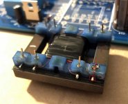
You can see in that photo where the wire attaches to the pin near the outside. You could take a small piece of wire or a thin resistor lead and attach it to that point, then bend it down and put through the PCB.
Missing one pin will still be mechanically strong, and you'll have a working preamp. 🙂
EDIT: This post brought to you by somebody who didn't refresh the page...
Missing one pin will still be mechanically strong, and you'll have a working preamp. 🙂
EDIT: This post brought to you by somebody who didn't refresh the page...


Following up with the 2016 board, stereo.
I changed my speakers from Pioneer SP-FS-51LR to Polk lsi15. This increased the hum. I cut the ground trace and this resolved the issue.
Still sounds sweet, with babelfish 2j as the amplifier.
Thanks again ZM !
I changed my speakers from Pioneer SP-FS-51LR to Polk lsi15. This increased the hum. I cut the ground trace and this resolved the issue.
Still sounds sweet, with babelfish 2j as the amplifier.
Thanks again ZM !

Sooo, all assembled but no sound unfortunately. Seems like the relays are not working (i.e. I can't hear them clicking). Just to double check: To close a relay I connect + to the relevant relay? (Usually via the twister board) I tried with two dupont wires as well and no clicking... They click only when I checked continuity between PSU ground and the relays.
I'm a bit at a loss here... anything specific I should check? All diodes seem to be in the right direction. Relays are RY-24W-K.
I'm a bit at a loss here... anything specific I should check? All diodes seem to be in the right direction. Relays are RY-24W-K.

here we go
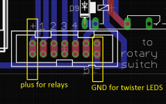
pretty much everything clear - connect "plus for relays" with vertical pair of pins for relay of choice (1 to 5)
for check, you can measure between plus and minus pins, expecting something as 24V
take care that these both rails are not having anything with audio GND, they're made from positive and negative rail before regs
I wrote "GND for twister leds" , where it is in fact "minus for twister leds", from reason explained in previous sentence
I'm lazy to edit picture
Attachments
Last edited:
check placement of two diodes around IRF510 in relay reg
one is protection for Ugs (anything between 6V8 and 12V will do) second is 27V, giving around 24V at output
I can bet that you switched their places
one is protection for Ugs (anything between 6V8 and 12V will do) second is 27V, giving around 24V at output
I can bet that you switched their places
- Home
- Amplifiers
- Pass Labs
- What's wrong with the kiss, boy?