Started without coffee....large mess up! What am I thinking!
What is quick and dirty way to rig an input?
Russellc
What is quick and dirty way to rig an input?
Russellc
if you think of enabling relay , that's easy - explained earlier in thread , few days ago
14 pins IDC connector : short pins 1 and 3 for input 1
1 to 5 for input 2
1 to 7 for input 3
1 to 9 for input 4
1 to 11 for input 5
14 pins IDC connector : short pins 1 and 3 for input 1
1 to 5 for input 2
1 to 7 for input 3
1 to 9 for input 4
1 to 11 for input 5
Use the K1 inputs
Jumper header position 1 to position 3
Whoops....per phone call I thought we decided jump #2 and #4 to turn on relay #1?
Russellc
if you think of enabling relay , that's easy - explained earlier in thread , few days ago
14 pins IDC connector : short pins 1 and 3 for input 1
1 to 5 for input 2
1 to 7 for input 3
1 to 9 for input 4
1 to 11 for input 5
I have 2016 boards if that matters, per phone call with Jim, I should connect #2 and#4 to turn on one...however in post above, slightly different #723...add to that I did all this with no coffee (nice dark Sumatra now) combined with professional level ability to destroy anvil with rubber hammer
Check your schematic, and check your board with a DMM. Per the schematic you sent me, pins 3 and 4 are electrically the same. Pins 1, 2, 13, and 14 are electrically the same. Take your pick.
Last edited:
Edited to add - just read back a bit... trust Jim, and ZM... and very sorry to hear about your blown cap! 🙁
Have trusted them for many years...also well aware of my propensity to mess up perfect info. Now to go hunt up a volume pot for temp use. Think 50K would work? Usually go with 25K but this one is right here...can change later if needed.
Russellc
Russellc
Sorry - I meant trust them over me... I failed to read back that they already answered you. DOH!
Yep, both will work just fine if you're not using (some) tube sources. Pick your fave. BTW - I learned that from Jim and ZM. 🙂
Yep, both will work just fine if you're not using (some) tube sources. Pick your fave. BTW - I learned that from Jim and ZM. 🙂
I've been searching for 2 hours at least for those two 50k Pots! Had them in hand just a week or two ago. I guess I could wire it "potless" for now, use computer for source and it's volume. The hunt continues.
Russellc
Russellc

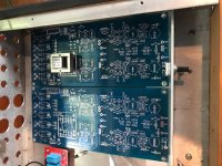
I got the Gemini shunt sections soldered up and tested with load resistors. I was only able to get a max of +/- 11v regulated out of them. After trouble shooting I realized I got 2.5v lm336’s instead of 5v.
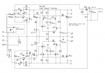
Does anyone think I should order replacements or can I swap out the upper voltage divider resistors R10 and R7 for a higher value, say ~100k?
Does anyone think I should order replacements or can I swap out the upper voltage divider resistors R10 and R7 for a higher value, say ~100k?
alter voltage divider, see what's value of LTP resistor (error correction amp) in Iron Pumpkin , where I did use 2V5 ref.
if you point me at your actual schm. I'll be more precise
btw. with shunt regs you don't need shunt res. for testing; final shunt element (mosfet) must be able to do all work
if you point me at your actual schm. I'll be more precise
btw. with shunt regs you don't need shunt res. for testing; final shunt element (mosfet) must be able to do all work
I am using all the values from this schematic except for U1 and U2 where I used 2.5v instead of 5v ones. With my limited knowledge I was thinking I could up the R10 and R7 values to get voltage division lower?
Thanks for tip on load resistors, I won't bother tacking them on for second board I test! 🙂
Thanks for tip on load resistors, I won't bother tacking them on for second board I test! 🙂
Attachments
Russ, is it working by today ?
or you are busy with Orthodox Easter, too ?
🙂
No, heating Iron now to put volume pots in the works. Then re fire & remeasure then to amp and speaks.
Russellc
- Home
- Amplifiers
- Pass Labs
- What's wrong with the kiss, boy?