There is something wrong with noise floor.Hello WLS-builders,
today I made my first measurements with my Focusrite Scarlett and REW on one of my
WLS-variants (variant3 = 2sk2394 ONSEMI JFets // 2N5551/2N5401 // output MosFets FQP3N30 /FQP3P20).
My signalgenerator from my Laptop puts out a sinus - signal (1 kHz) with a voltage swing of 0,068V (68mV).
Measured with my Fluke at the output (headphone out). Pretty low.
At the output of my WLS variant3 I have measured a voltage swing of 1,308 V AC at 1kHz (volume pot close to full volume). If I am hopefully right, this would equal a gainfactor of 19,23 or circa 25,6 dB.
Slightly higher 2nd harmonic distortion than 3rd.
Only some impressions. I hope I did not measure nonsense? 🤔
Cheers
Dirk 😉
Do the loop first, no pre, just the output from scarlet to its input. Set the levels right, you should get -130 to -140 dB down.
Hello ZenMod,
the inputsignal is generated by a software/signalgenerator from my laptop (battery driven - to avoid more
noise from the laptop -smps).
That 1 kHz -sine-wave (0,068 V AC) is sent from laptop / headphone out into the input of the preamp.
At the output of the preamp the signal is sent to the Focusrite Scarlet (to the line input).
From the Focusrite Scarlet the signal goes into my PC (not my laptop) with REW.
So I didn't made a loop measurement = REW as signalgenerator and analyzer.
I hope this is understandable?
Cheers
Dirk 🙂
Hello Ben Mah,
Thanks for the hint! I already read in the recommended thread.
I have to get through my 'personal training and learning programm' with REW / Focusrite Scarlet.
But I think, that the problem in my WLS_variant3 is also the high gain and noise I get over the rails.
But i will report back, if I got a little bit 'smarter'.... 🙄 - 🤓
The noisefloor of the measurement setup got down to circa -130 dB (as Adason mentioned above).
Cheers
Dirk

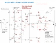
This is the schematic with parts-changes I have done.
If you want to try this: no guarantee or responsibilities from my side!
You do this on your own risk! I am still playing with this.
The JFets have been carefully matched (two quartets)
All BJTs have been carefully matched NPN-PNP (HFE at 180)
The MosFets in the outputstage have been matched N-Mos - P-Mos.
All actives have been matched from left channel to right channel.
Rails are on +-20 V DC.
0,162 V over 3.3 Ohm bias resistors in outputstage = 49 mA
Cheers
Dirk 🙄
Attachments

I'm planning on my Fall project to be this linestage. I roughed out the cost of it and get somewhere in the $700 range. This includes case, switches, (hopefully) everything. I have included some XLR output jacks as well as I will be driving my ACA pair in balanced mono. I also plan on using a VRDN as the power supply.
As always, questions abound.
If I am building a balanced version do I need 2 VRDN supplies?
Are all the board parts in the parts kit in the store (output devices, etc)? I'm assuming so but just checking.
I have not wrapped my head around it yet, but is there a specific way to configure having one balanced input device along with one or more single-ended input devices? I believe this is calculated with R18 and R20. I'm sure someone has built a WLS with both types of inputs. This is diyaudio after all!
Finally, with the configuration mentioned, is there something specific I need to do to enable having balanced output plus an optional single-ended output? And I'll bet someone has built the WLS with both types of output.
If a previous post is easier in explaining any of this, feel free to reference me there. I'm slowly reading through the thread.
Many thanks! bh
You would need two line stages to do balanced outputs. You could go with two power supplies but you should only need one. The parts kit for the linestage is complete with everything you need to populate the board.
I believe to make a balanced output single-ended, you would tie negative and ground together. However, with having two linestages to make a balanced output, I am not sure if it would work. Also, going balanced nulls out some of the distortion. Maybe try it single-ended and brainstorm how to make it balanced in the future. I was going to go balanced with it but it sounds really good so I haven't...
I just installed a Salas I-select input switch board and a Khozmo stepped attenuator into mine. None of my other preamps get the same treatment...
Great news! I built the B1 - and it's now as quiet as can be. Using the BA 2018 as an headphone amp and it sounds amazing as well. Really digging both setups. Thank you!!The buffer(s) take care of impedance issues, that you might otherwise encounter with just a volume control between the source and power amp.
also beware that running balanced adds 6db gain. If you use source «that is a hundred times better being run balanced than single ended», according to the manufacturer, simply change the source 🙂
You would need two line stages to do balanced outputs. You could go with two power supplies but you should only need one. The parts kit for the linestage is complete with everything you need to populate the board.
Correct. I have factored in the second pair of boards for balanced. The "should" in your next sentence, though. I'd like to know for sure.
Maybe try it single-ended and brainstorm how to make it balanced in the future.
If I have two sets of boards, then the output can be balanced easily. I still wonder how to configure a single balanced input when there will be other single ended connections. I guess I'll keep digging into the thread Thanks, Mike.
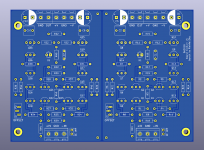
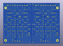
After a few cosmetic and not changes I sent my fully through hole version in production.
Those boards would be blue color, lead free HASL and 2mm thickness.
There was also an option to convert it free to ENIG for free if fab so decide but I think it will end up HASL.
Feel excited because it's the first time I sent something I made in KiCad to manufacture.
So I am patiently waiting now. 🙂
Attachments
That looks great! That is a milestone. Let us know how it works after you get a chance to play with it 🙂
Hello RainfallSky,
I hope you will have the same fun with your version of WLS, as I still have.
This is a great circuit!
 🎸
🎸
Thanks to Wayne!
Cheers
Dirk 😉
I hope you will have the same fun with your version of WLS, as I still have.
This is a great circuit!
🎸Thanks to Wayne!
Cheers
Dirk 😉
Thank you Dirk! Part of the fun has already begun. 😀I hope you will have the same fun with your version of WLS, as I still have.
It seems ordering KSA992 / KSC1845 require a lot of time to deliver.
I found Toshiba 2SA966 / 2SC2236 locally from a trusted seller and I though maybe I could use them.
Would they be okey in place of Q5-7, Q11-13? Is Cob up to 40pF could be a problem?
(Datasheet from year 1997 said Cob is 30pF max, and datasheet year 2009 said Cob is 40pF tyical.)
I found spice models for those Toshiba transistors and tryed to simulate linestage with them in place of Q5-7, Q11-13.
Barely anything changed but I could be missing something.
At Q9, Q14 I was planning to use BD139 / 140, and 2SA1837 / 2SC4793 at Q8, Q10.
- Home
- Amplifiers
- Pass Labs
- Wayne's BA 2018 linestage