I like using them. They keep RFI in and out.Does anyone use emi filters? I bought this one locally at an electronics store but wondering if it’s worth adding to my preamp build.

Hello Dneu2011,
although I am repeating Wayne - I use EMI - filters in all of my PSUs.
I like the Schaffner - filters. But that is my personal preference.
Keeping some 'electrical - dirt' out before struggling with it later... 🤔
Can we hear it? - I don't know.
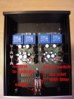
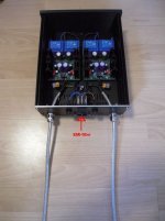
On the pic is the PSU for my WLS. You can see the EMI-filter.
Cheers
Dirk 🙂
although I am repeating Wayne - I use EMI - filters in all of my PSUs.
I like the Schaffner - filters. But that is my personal preference.
Keeping some 'electrical - dirt' out before struggling with it later... 🤔
Can we hear it? - I don't know.
On the pic is the PSU for my WLS. You can see the EMI-filter.
Cheers
Dirk 🙂
Attachments
I have a newish kit with the 'heavy duty' transitors being marked A004B and C004B. Which of these goes where?
I ended up adding one. Thanks for the advice!!Hello Dneu2011,
although I am repeating Wayne - I use EMI - filters in all of my PSUs.
I like the Schaffner - filters. But that is my personal preference.
Keeping some 'electrical - dirt' out before struggling with it later... 🤔
Can we hear it? - I don't know.
On the pic is the PSU for my WLS. You can see the EMI-filter.
Cheers
Dirk 🙂
I thought of the PNP check, etc, but I don't trust myself on this. I can build these things, because I can follow directions, but that's about it.
It appears that the A004B is PNP, so replaces the KSA1220, and the C004B is NPN, so replaces the KSC2690.
I didn't realize the Mega 328 could do that. It also helped me figure out which way around they go: The printed side is basically the 'flat' side.
It appears that the A004B is PNP, so replaces the KSA1220, and the C004B is NPN, so replaces the KSC2690.
I didn't realize the Mega 328 could do that. It also helped me figure out which way around they go: The printed side is basically the 'flat' side.
I bought some nice NOS low noise precision resistors locally that I plan to use in Wayne's LS.
Need advice to decide resistor for R6.
One I have is 1.5k 0.25% 25ppm and second is 1.2k 0.05% 10ppm.
R6 then will share current with P1 100ppm trimmer...
I then tryed to simulate how current and dissipation will split between the two.
Ver. 1 (original):
R6: 1.5k - 1.3771598mA / 2.8448537mW
P1: 1.253k - 1.6486361mA / 3.4056509mW
Ver. 2:
R6: 1.2k - 1.7214515mA / 3.5560739mW
P1: 1.584k - 1.30413mA / 2.6939954mW
Ver.2 seems nice.
Less current through 100ppm trimmer, less heat if we can say 0.7116555mW differece have any significance in this case.
What do you guys think?
One more ready for juice 🙂
I dont have a lot of faith in how I attached those SMDs....first time.
ZM, can you give a link to the right kind of flux? I just built three of these boards without it. I looked closely at the results, and the SM parts seemed OK, but I guess we'll see. I'd hate to have to redo them.
I assume the trimmer is rated for 500mW and the resistors for at least 250mW. The reality is they will probably not experience any noticeable change in temperature and resistance from the small amount of current flowing through them so either combination would be stable.I bought some nice NOS low noise precision resistors locally that I plan to use in Wayne's LS.
Need advice to decide resistor for R6.
One I have is 1.5k 0.25% 25ppm and second is 1.2k 0.05% 10ppm.
R6 then will share current with P1 100ppm trimmer...
I then tryed to simulate how current and dissipation will split between the two.
Ver. 1 (original):
R6: 1.5k - 1.3771598mA / 2.8448537mW
P1: 1.253k - 1.6486361mA / 3.4056509mW
Ver. 2:
R6: 1.2k - 1.7214515mA / 3.5560739mW
P1: 1.584k - 1.30413mA / 2.6939954mW
Ver.2 seems nice.
Less current through 100ppm trimmer, less heat if we can say 0.7116555mW differece have any significance in this case.
What do you guys think?
But if you go strictly by the numbers Ver. 2 is better but it really is a moot point.
And the 0.25% or 0.05% precision is of no consequence since the final resistance is fine tuned by the trimmer.
ZM, can you give a link to the right kind of flux? I just built three of these boards without it. I looked closely at the results, and the SM parts seemed OK, but I guess we'll see. I'd hate to have to redo them.
will look ASAP
you can redo soldering - just blob of flux at JFET and do it
recheck soldering with beep test - one tip to JFet pin, second tip to any other pad on same trace
ZM, can you give a link to the right kind of flux? I just built three of these boards without it. I looked closely at the results, and the SM parts seemed OK, but I guess we'll see. I'd hate to have to redo them.
see what I'm using https://botland.store/rosin-resin-a...k83-for-soldering-smd-50ml-5901764329510.html
easy to remove residue (even if not needed) with some cotton fluff and alcohol
find something similar/same on your neck of wood
I assume the trimmer is rated for 500mW and the resistors for at least 250mW. The reality is they will probably not experience any noticeable change in temperature and resistance from the small amount of current flowing through them so either combination would be stable.
But if you go strictly by the numbers Ver. 2 is better but it really is a moot point.
And the 0.25% or 0.05% precision is of no consequence since the final resistance is fine tuned by the trimmer.
Thank you Ben!
Those particular resistors is 125mW but with big body like Dale RN55.
Simulation with 18V shows that the biggest load is 27.3mW at R7, R13 then 15.3mW at R9 and everything else is even less.
I guess I am safe.
Those resistors are RATED for 125mW, but being RN series are mil-spec, and that spec requires 100% overhead… so they are actually 250mW CMF55, with the datasheet saying they are 125mW. (And non-RoHS tinned leads… 🙂 )
Yes yes I know.Those resistors are RATED for 125mW, but being RN series are mil-spec, and that spec requires 100% overhead… so they are actually 250mW CMF55, with the datasheet saying they are 125mW. (And non-RoHS tinned leads… 🙂 )
I was meant to say that I have found different resistors locally that are 125mW ratred but have as big body as RN55/CMF55.
Acually a little bit bigger than RN55 but smaller than RN60.
My speculation that it could be because they are old design and was declared as precision resistors.
Anyway I plan to use them and even 125mW resistors shoold be safe for Wayne LS currents.
Sounds like a good plan.
The bodies of through-hole resistors seems to be shrinking quite a bit - these are 400mW resistors with bodies smaller than 125mw of only a few years ago. Neat!
(250mW Vishay/Beyschlag for scale, which is similar in size to the CMF55/RN55 Dales)


The bodies of through-hole resistors seems to be shrinking quite a bit - these are 400mW resistors with bodies smaller than 125mw of only a few years ago. Neat!
(250mW Vishay/Beyschlag for scale, which is similar in size to the CMF55/RN55 Dales)

- Home
- Amplifiers
- Pass Labs
- Wayne's BA 2018 linestage