Right? They are small enough that reading the stripes is a bit challenging.

But it is so tedious to replace every resistor if you already have resistors. I did it for 6-24 active crossover, but in the case of the SissySIT package deal I think I will leave everything original.you know what Pa sez why Dale are good ...... 🙂
Pa sez that "Dales are sooooo good - value is actually written on them not coded"
Yep, very convenient. But only if I remember to direct the value upwards before soldering.Pa sez that "Dales are sooooo good - value is actually written on them not coded"
Adasons simple active crossover uses so few components that I am tempted to use foil resistors.
Here's what mine did when powered up:

Wayyyyyyyy too much smoke to want to continue, or try to unravel.
Going to do an iron pre instead next. Already have too much gain anyways. Perhaps I'll return to this one later.
🙁
Wayyyyyyyy too much smoke to want to continue, or try to unravel.
Going to do an iron pre instead next. Already have too much gain anyways. Perhaps I'll return to this one later.
🙁
Hope it turns out allright! Jfets are the main culprit in this circuit. Always start ANY troubleshooting there.ZM, can you give a link to the right kind of flux? I just built three of these boards without it. I looked closely at the results, and the SM parts seemed OK, but I guess we'll see. I'd hate to have to redo them.
MZM tought me, and I have passed this advice along many, many times: use flux on those legs, preferably liquid and not grease. Then carefully and thoroughly clean it all off. Take care around the JFET to rinse it all. I bathed it all in alcohol several times. Ps: don’t rush, let it all dry before applying power 🙂
Then, verify with beep test or ohmmeter solder joints by connecting one probe to jfet legs, and the other to next point on PCB, usually a resistor leg. If resistance is low/beep test checks out ok, you are probably OK. If not, resolder, those joints can look OK and not be.
Be very careful if you replace a JFET, so you don’t damage the pcb underneath. Also, make sure no flux is left under the jfet.
PS: unstable offset, in any degree, is giveaway number one. It should drop slowly slowly and then settle. Any jumping, you need to redo your work.
It is a fantastic preamp. As long as you need the gain.
Good luck! 🙂
Last edited:
You can adjust the gain easily with two resistor changes. Can't remember the exact two, but it is somewhere in this thread, I think Mark Johnson replied to me with the answer. Also did both sides go up in smoke?
Just the left channel, and it was a fairly dramatic death.
Let my board be a cautionary tale....I should have cut those jfets loose and done exactly as ZM said. Poked the bear instead, got the claws.
Thats the first time I've had that happen.
Let my board be a cautionary tale....I should have cut those jfets loose and done exactly as ZM said. Poked the bear instead, got the claws.
Thats the first time I've had that happen.
Increase R17 to reduce gain without adjusting the feedback network. However, I did this, imho it just didn’t sound the same.You can adjust the gain easily with two resistor changes. Can't remember the exact two, but it is somewhere in this thread, I think Mark Johnson replied to me with the answer. Also did both sides go up in smoke?
Gain is R16/R17 +1Increase R17 to reduce gain without adjusting the feedback network. However, I did this, imho it just didn’t sound the same.
Here is the sim experiment with a gain of 3.
Sim is my version of parts but you can see the idea.
V1 is R16 20k, R17 10k.
V2 is R16 30k, R17 15k.
Same V out.
Attachments
Very nice! Could you consider simming R17 @ 20 and 25k, leaving the feedback resistor at stock 27k?Gain is R16/R17 +1
Here is the sim experiment with a gain of 3.
Sim is my version of parts but you can see the idea.
V1 is R16 20k, R17 10k.
V2 is R16 30k, R17 15k.
Same V out.
Btw: it might be interesting for the greedy boys to know whether the sims show increased tendencies of oscillation in changing these values
Last edited:
With my parts? Classic linestage looks like a THD H2 H3 generator machine in my sim..Very nice! Could you consider simming R17 @ 20 and 25k, leaving the feedback resistor at stock 27k?
Btw: it might be interesting for the greedy boys to know whether the sims show increased tendencies of oscillation in changing these values
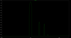
Okey here is more classic linestage with Toshiba TTC004B / TTA004B at the outputs.
V1: R16 27k, R17 20k
V2: R16 27k, R17 25k
Noise floor drops with lower gain.
Attachments
Thank you!! 🙂With my parts? Classic linestage looks like a THD H2 H3 generator machine in my sim..
Okey here is more classic linestage with Toshiba TTC004B / TTA004B at the outputs.
V1: R16 27k, R17 20k
V2: R16 27k, R17 25k
Noise floor drops with lower gain.
This is the first time I’ve heard of one releasing the smoke… can you post a photo or two so we can try to autopsy?
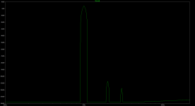
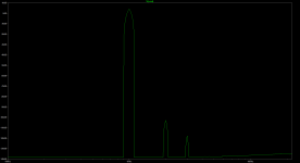
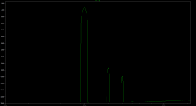
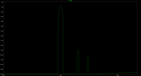
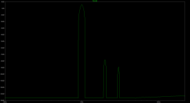
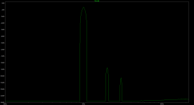
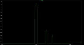
Those was with 15V, now with 18V.Thank you!! 🙂
V0: R16 27k, R17 10k (3.7 gain) 15V
V1: R16 27k, R17 10k (3.7 gain) 18V
V2: R16 27k, R17 20k (2.35 gain) 18V
V3: R16 27k, R17 25k (2.08 gain) 18V
Attachments
Certainly 😉
I know whatever transpired here was somehow my fault...
Pre-smoke:

Post-smoke:

I pitched the whole thing in the trash after it went up in flames, so theres a little gradu on there from that. Wanted to make sure I wasnt tempted to pilfer parts that could cause future problems.
I used the same regulated supply in a temp case I've used with my BA3-FE and NuTube preamp. I did relocate the PS boards in the case but a quick check with the meter had it putting out 24v unloaded, business as usual, before I connected this one.
I know whatever transpired here was somehow my fault...
Pre-smoke:
Post-smoke:
I pitched the whole thing in the trash after it went up in flames, so theres a little gradu on there from that. Wanted to make sure I wasnt tempted to pilfer parts that could cause future problems.
I used the same regulated supply in a temp case I've used with my BA3-FE and NuTube preamp. I did relocate the PS boards in the case but a quick check with the meter had it putting out 24v unloaded, business as usual, before I connected this one.
- Home
- Amplifiers
- Pass Labs
- Wayne's BA 2018 linestage