Hi, rookie question here: I have a pearl 2 built but wanted to combine Wayne's Linestage with it. Is the Pearl 2 power supply too high for the linestage?
Thanks!!
Thanks!!
What voltage is your Pearl 2 PSU?Hi, rookie question here: I have a pearl 2 built but wanted to combine Wayne's Linestage with it. Is the Pearl 2 power supply too high for the linestage?
Thanks!!
everything from 15-24vdc is fine. 27-28 is not exactly fine, but perfectly OK. Just ensure the output devices don’t blow (ie sinking, ventilatipn etc). Sweetspot on this linestage is 18-20vdc.
regards,
Andy
Hello RainfallSky,
hello all others, who want to experiment with Waynes Line Stage,
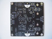
I made also my own pcbs of the WLS. Why? I wanted to be more flexible with some parts and
adjustments.
Don't misunderstand me - the original pcb from the store is pefectly fine! I have built 2 WLS
on the original boards.
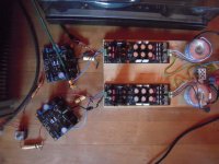
Some pics and what I have changed.
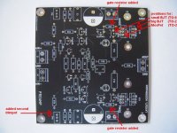
I changed the pcb in the outputsection to be able to use
TO-92 BJTs, TO-220 BJTs and TO-220 MosFets (for the MosFet I added a position for a gate-resistor).
I added a second trimpot on the negative side of the rails
I added a second position for another LED or any other part (like a resistor) in the outputstage
Cheers
Dirk 😉
hello all others, who want to experiment with Waynes Line Stage,
I made also my own pcbs of the WLS. Why? I wanted to be more flexible with some parts and
adjustments.
Don't misunderstand me - the original pcb from the store is pefectly fine! I have built 2 WLS
on the original boards.
Some pics and what I have changed.
I changed the pcb in the outputsection to be able to use
TO-92 BJTs, TO-220 BJTs and TO-220 MosFets (for the MosFet I added a position for a gate-resistor).
I added a second trimpot on the negative side of the rails
I added a second position for another LED or any other part (like a resistor) in the outputstage
Cheers
Dirk 😉
Attachments
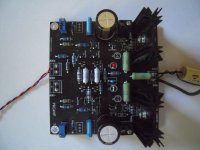
This is the first variant I have tried:
It needed some time to get it running. There had to be done changes to a lot of resistor values and to the trimpots. But it sounds very nice...
Cheers
Dirk 😉
- changed JFets to Onsemi 2SK3557
- changed all small BJTs to Zetex ZTX 851/951
- changed output BJTs to Toshiba TTA/TTC004B
It needed some time to get it running. There had to be done changes to a lot of resistor values and to the trimpots. But it sounds very nice...
Cheers
Dirk 😉
Attachments


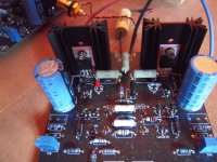
The third variant:
JFets: Onsemi 2SK2394
BJTs: Onsemi 2N5551/2N5401
MosFets (outputstage): Fairchild FQP3N30 / FQP3P20
The JFets have been chosen because of their very high yfs and they are super low noise.
The Mosfets in the outputstage are heavily biased - hot.
I am still testing, adjusting and listening to this version. I like it!
But some of my poweramps are overdriven from this little beast. gain-structure....
I will not be able to answer questions today. I will be on a 2-wheeled-'amp' this sunny afternoon...
Cheers
Dirk 😉
Attachments

If you want to use 2SK2394, you should set the cascode voltages to say +/-9V or less.
Can go as low as 5V.
Patrick
Can go as low as 5V.
Patrick
But I want to have something that can drive 30 ohm headphones and still have no distortion.
So I used the same approach as the Pioneer Super Liunear, namely Darlington output pair.
Now distortion is very respectable even at 2Vrms into 30R.
I also find that changing R23 from 330R to 1k will improve the phase marginat gain >3.
So feel free to play around in Spice. It is free. 😉
Patriick
.
I played with Patrick's LTSpice files and it does look very Interesting if I didn't made mistakes.
Attachments
So how does this improve on the one posted in #685 ?
https://www.diyaudio.com/community/threads/waynes-ba-2018-linestage.329240/post-5778855
And why would you want 6x lower bias for the output transistors than the Darlington drivers ?
Patrick
https://www.diyaudio.com/community/threads/waynes-ba-2018-linestage.329240/post-5778855
And why would you want 6x lower bias for the output transistors than the Darlington drivers ?
Patrick
Anyone have any 2sk209-GR for sale? Appears mouser and digikey are out of stock.
also looking for a PSU board if anyone has one.
Thanks!
also looking for a PSU board if anyone has one.
Thanks!
https://hken.rs-online.com/web/p/jfets/2363556
Not sure how to buy from RS at your location.
https://www.arrow.com/en/products/2sk209-gr-te85lf/toshiba
Patrick
Not sure how to buy from RS at your location.
https://www.arrow.com/en/products/2sk209-gr-te85lf/toshiba
Patrick
No, I am afraid it's not improvement but just me playing in ltspice, and honestly sometimes with lack of fully understanding what I actually do.So how does this improve on the one posted in #685 ?
https://www.diyaudio.com/community/threads/waynes-ba-2018-linestage.329240/post-5778855
And why would you want 6x lower bias for the output transistors than the Darlington drivers ?
I was too attracted only to 2H 3H levels.
I went ahead and just paid the high $22 shipping, but I bought 40 of them if someone wanted to pay for a set of 8, I will have extra.https://hken.rs-online.com/web/p/jfets/2363556
Not sure how to buy from RS at your location.
https://www.arrow.com/en/products/2sk209-gr-te85lf/toshiba
Patrick
Hello
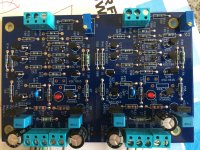
I have assembled the kit from the store but 1 channel isn’t working.(Left side of PCB is ok)
I have opted for the most powerful output devices.
The defective side has the led dimmed and the output is at nearly full negative rail. The trim pot P1 has no effect on the DC offset but without being powered P1 is working well and the overall resistance made from R6//P1 varies properly when turning P1.
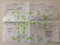
I’m attaching the schematic with voltage reference to Gnd.
Top value is from the working channel and bottom ones from defective (right side of PCB)
Hope a good samaritain can help.
Thanks a lot.
Eric
I have assembled the kit from the store but 1 channel isn’t working.(Left side of PCB is ok)
I have opted for the most powerful output devices.
The defective side has the led dimmed and the output is at nearly full negative rail. The trim pot P1 has no effect on the DC offset but without being powered P1 is working well and the overall resistance made from R6//P1 varies properly when turning P1.
I’m attaching the schematic with voltage reference to Gnd.
Top value is from the working channel and bottom ones from defective (right side of PCB)
Hope a good samaritain can help.
Thanks a lot.
Eric
Attachments
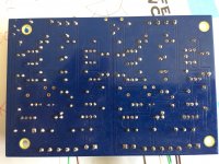
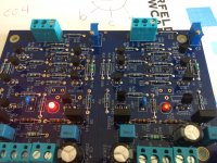
Try reflowing your solder joints on the 2sk209 fets. I had a similar issue and found it was a bad solder.
Maybe just a photo but it looks like Q16 at the bottom of the board have 2 pins connected by a solder drop.
- Home
- Amplifiers
- Pass Labs
- Wayne's BA 2018 linestage