I'll let someone more familiar with your power supply board respond, but I'm guessing the thin yellow wire goes to your chassis ground THROUGH a ground breaker as described in post #3977, he labeled it ground coupler.

Ok. I’ve replaced R3s and reconnected the transformer to the board in the correct way and I’ve got a stable 17.9V+ on one side and 17.7V- on the other, which I suppose means the PSU board is otherwise undamaged?
Might be fine, expected voltage is a good sign.
I’ve got the ground from the AC inlet and the ground from the transformer connected very securely to the chassis and tested 0.0R resistance to the currently-fitted chassis panels and I’ll confirm for additional panels as I add them back.
Good
the third, thinner yellow wire goes nowhere as yet but I think that joins to my signal ground?
Chassis, and possibly through a ground-loop-breaker as suggested, however if you don't have that, just attach to chassis for now.
I’ve connected the linestage boards as I understand they should be connected but, reading back I’m wondering if the 6 leads should be split into two where they come together and twisted together as channels, rather than all as one bundle. Would that make a difference?
Eh. Maybe. Doesn't matter much, it's DC.
I haven’t switched it on yet with the BA2018 boards connected so one might yet be busted but I’ll wait for the all-clear before I throw the switch 🙂
Give it a go!
The third yellow wire - where does it originate?
A picture showing the whole project, including wiring to the AC IEC connector, would be informative. Include a photo from above.
The power supply voltages look good. The wiring looks correct. It will work the way you have bundled them. However they might be a bit better if the V+ V- G wires to each channel are twisted together. The only difference is that the way you have them bundled there is less separation of the channels.
I agree with @6L6, you can just ground the thin yellow wire to the chassis ground for now. If there is no humm, there is nothing to fix. If there is humm, then you could try the ground breaker.
Sweet. Thanks.
Running around after a sick 8yo today so will steal time where I can
Running around after a sick 8yo today so will steal time where I can
All connected and playing. Thank you!
One of the line stage channels had a dry joint somewhere so I reflowed a bunch of the connections on both for peace of mind.
The reality of my earlier soldering job did not match my memory of it. I’m much better at it now.
All in all, a good reminder to myself that “it was working before” is not the same as “it’s done correctly”
I haven’t put it through the input selector etc yet but I’m pretty sure I know what I’m doing there (famous last words🙄)
If your goal is to protect the switch contacts from inductive flyback (huge voltages!) when the switch opens (and dI/dt equals minus infinity!),
then I recommend providing a flyback return current network a/k/a "snubber" as shown below. This has the advantage that it does not contain a circuit path allowing AC current to flow, when the switch is in the OFF position. Capacitor-across-the-switch-contacts includes an AC current path from mains, to transformer primary, and back out to mains. Even at 60 Hertz. Even when the switch is off.
_
Mark & Co.:
Sorry for the off-topic question, but I trust this won't be a huge distraction. I'm building an integrated chip amp with my younger daughter and would like to implement a snubber as suggested by Mark. How do I calculate the resistor and capacitor values where the transformer is 300 VA?
Thank you!
Regards,
Scott
Scott, are you using an Antek transformer? There may be R information in the thread “Quasimodo results only”
Hey y'all boyz:
S. R. McGee is talking about an arc suppressing snubber to protect a power on/off mechanical switch -- not a transformer secondary ringing prevention snubber of the Quasimodo persuasion. Follow the hyperlink that SRM put in his post; it takes you to post #3230 where, as Ed McMahon of The Tonight Show often said, a child of four can plainly see . . . . . . it's an arc suppressor.
How do you calculate appropriate values for the arc suppression components? Let's see what the wise membership of diyAudio has to say about that.
Calculate? No idea. Pass uses 3300pF X1-rated caps that spark suppress the switch and do a little line filtering. I just blindly use those as I have a bag full of them... Seems to work so far.
How do I calculate the resistor and capacitor values [for a 115VAC on/off switch arc suppressor] where the transformer is 300 VA?
The market leader and "big gorilla" in this product space is called Quencharc, made and sold by Cornell-Dubilier and its licensees. Unfortunately Mouser offers Quencharc parts {containing one R and one C!} for ten US dollars. Ouch!
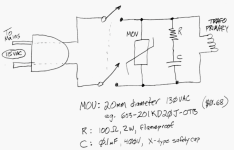
Luckily, Cornell Dubilier published a one page technical brief called "How Quencharc Works" which I am sure Google will find quickly. At the very bottom of the page, it left-handedly offers blanket advice: Buy our 100R + 0.1uF Quencharc, connect it in your product, and then use an oscilloscope to verify that arcs are fully suppressed. If arcs are NOT fully suppressed, just add a Metal Oxide Varistor in parallel and sleep soundly.
So I looked up Metal Oxide Varistors in the Mouser catalog and found that the ones rated "130V AC" appear to be a comfortable fit. In my opinion. 130V AC varistors won't fire under normal 115VAC mains operation, but they will fire if the switch contacts experience an arc event, even a mild one. And they cost less than a dollar so you still save Big Bucks building a three component arc suppressor, compared to paying for a Quencharc.
Schematic attached below.
_
Attachments
Power switches? We don’t need no stinking power switches.
Hi folks,
If I was going to use a volume pot with this linestage what is the recommended value and how would I install it?
If I was going to use a volume pot with this linestage what is the recommended value and how would I install it?
- Home
- Amplifiers
- Pass Labs
- Wayne's BA 2018 linestage