I looked at the avdesignguru board in 2696. I opened up the gerbers on JLCPCB to see the board. Looks nice. Pete's looks very sharp too. Did you notice a difference in sound characteristics between the three power supplies? I hear a lot of talk about Salas's regulators etc. I used his I-select which is a very nice product.
Very little difference. The use of Sparkos regulators in avdesignguru's enhanced the sound from one of my 2018 builds slightly while Pete's allowed me to build in a slightly smaller chassis. Stock builds..I'd say Pete's had the slightest edge to my ears, but that's my ears on my system. Wayne's linestage is just a fantastic sounding preamp period! Either the Salas or the Super-reg are another purists path to follow if you rather use a plain toroidal (right to the Salas) or toroidal to PS to Super-reg; they just involve a slight bit more work....the Salas needs to have its power mosfets & shunt elements mounted to the chassis for heat sinking (they can get really warm) while the Super-reg needs to have special wiring implemented to work properly with whatever it's driving. Using either of these two regulator circuits guarantees the cleanest, regulated voltage to your BA2018.I looked at the avdesignguru board in 2696. I opened up the gerbers on JLCPCB to see the board. Looks nice. Pete's looks very sharp too. Did you notice a difference in sound characteristics between the three power supplies? I hear a lot of talk about Salas's regulators etc. I used his I-select which is a very nice product.

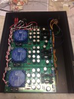
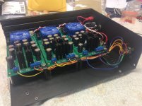
For what little it's worth, I was able to mount three of Pete Millett's power supplies in a Galaxy 2U 230x280mm chassis for my BA2018 preamp. Admittedly ridiculous, but I liked the idea of dual monaural and a supply for the attenuator system and the front panel LEDs. I'm sure any of the supplies suggested by turion64 would work fine (and you only need one), but Pete's is definitely more compact than the others.
Regards.
Regards.
Attachments
The VRDN dual voltage regulator PCB is 62 mm X 142 mm. Its output is adjustable over the range ±11V to ±20V and it'll deliver 1.5 amps on both V+ and V-. It's designed so you can drive it from either a single-secondary-winding transformer (e.g. an AC wall wart) or a two-independent-secondary-windings transformer (like an Antek or a Talema). The Gerbers are available for download on the diyAudio Forum -- just use the Search button.
I use a Salas Ultrabib with my WLS (and practically all other pre’s). It’s hard to beat.I looked at the avdesignguru board in 2696. I opened up the gerbers on JLCPCB to see the board. Looks nice. Pete's looks very sharp too. Did you notice a difference in sound characteristics between the three power supplies? I hear a lot of talk about Salas's regulators etc. I used his I-select which is a very nice product.
Folks:
I am building a simple BA2018 preamplifier for a friend. The preamp has a 50VA toroid, a Mark Johnson VRDN power supply, the BA2018 preamplifier, a relay board for source selection and some front panel LEDs. That's it. I understand it would be beneficial to place a small X2 or Y2 capacitor across the power switch to prevent arcing, but I don't know what value cap to use (or the formula for determining its ideal value).
Can someone enlighten me?
Regards,
Scott
The salas I-select has implementation for LEDs. Check it out. It's a nice little setup.
I used to use just a typical dual pole 4-way switch. I changed to the Salas specifically for the relays as they aren't as prone to oxidation. I wasn't really able to find a nice switch that would stay clean enough for the quality of signal that Wayne's line stage produces. You tend to know the things that aren't perfect with the BA2018
I used to use just a typical dual pole 4-way switch. I changed to the Salas specifically for the relays as they aren't as prone to oxidation. I wasn't really able to find a nice switch that would stay clean enough for the quality of signal that Wayne's line stage produces. You tend to know the things that aren't perfect with the BA2018
I understand it would be beneficial to place a small X2 or Y2 capacitor across the power switch to prevent arcing
If your goal is to protect the switch contacts from inductive flyback (huge voltages!) when the switch opens (and dI/dt equals minus infinity!),
then I recommend providing a flyback return current network a/k/a "snubber" as shown below. This has the advantage that it does not contain a circuit path allowing AC current to flow, when the switch is in the OFF position. Capacitor-across-the-switch-contacts includes an AC current path from mains, to transformer primary, and back out to mains. Even at 60 Hertz. Even when the switch is off.
_
Attachments

Last edited:
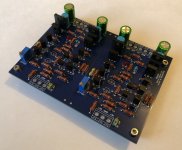
I am this far. 🙂
It seems I only have left matched 2SK170/2SJ74 pairs from punkydawg.
Maybe I should temporary put my 2SK170's from those pairs and then change them later.
Can anyone recommend sockets for TO-92-3 transistors?
I also have problems to find good quality terminals in stock locally.
Waiting for those would be long.
But I have oversized ones. 😀
Attachments
Just solder them but don‘t cut the leads. Leave them long - easy to remove later. There isnt really a socket made for the TO-92 package, you’d have to kludge something up from header pins.
When I desolder TO-92 devices, I put a big glob of solder across the tip of my soldering gun and touch all three pins at once or swipe the gun back and forth if I don't have that much room. I pull the top of the JFET with my fingers so I can meter how hot it gets. It takes a few seconds.
Hi RainfallSky,
I do socket my precious Toshiba JFETs in a lot of my builds. I'm using either something like these:
Precision Pin Header 2,54mm 1x3
or cut three off a longer strip ...
Precision Pin Header 2,54mm 1x36
😉
These are the same sockets that are used for ICs / OpAmps / Opto Couplers etc. So far, I have not have contact problems with these, even after several years.
Best regards,
Claas
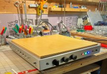
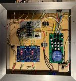
Just another day and just another build but Man, I am happy this version of the Waynes BA 2018 went so well! This time I use the Glass Audio A-3 Mini volume control with input selector instead of drill bit extensions and Pots. You can just barely see it (a small red board) in the open top shot with RCAs showing. I also went through my stash of three legged fuses and quality matched them to purpose and this time I was able to get the DC offset to almost zero. It bounces around a bit on my Fluke 179, +/- 2mV.
Yes, the three colors of LED on the front are superfluous but I can't resist ;-). The vintage knobs are another hobby of mine as is the working of (scrap) aluminum! I like the shiny stuff.
It's an amazing sounding preamp and in this format can become the platform for any stout (heavy) amplifier. Thank you all out there for your patience with me and with each other! We need more things that focus on our better natures eh? Top to bottom, I think you all very much.
Attachments
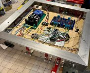
Very nice chassis design (that took a lot of work) but what are the holes in the side for? ...just for aesthetics?Just another day and just another build but Man, I am happy this version of the Waynes BA 2018 went so well! This time I use the Glass Audio A-3 Mini volume control with input selector instead of drill bit extensions and Pots. You can just barely see it (a small red board) in the open top shot with RCAs showing. I also went through my stash of three legged fuses and quality matched them to purpose and this time I was able to get the DC offset to almost zero. It bounces around a bit on my Fluke 179, +/- 2mV.
Yes, the three colors of LED on the front are superfluous but I can't resist ;-). The vintage knobs are another hobby of mine as is the working of (scrap) aluminum! I like the shiny stuff.
It's an amazing sounding preamp and in this format can become the platform for any stout (heavy) amplifier. Thank you all out there for your patience with me and with each other! We need more things that focus on our better natures eh? Top to bottom, I think you all very much.
I finished to solder my version of Wayne's LS this night.
Set DC out and tryed to listen with headphones.
There was a sound at the output but with distortion and also volume level was not even loud with LS connected directly to source.
Was dead tired to search what could go wrong and debug.
And I am still tired beacause I slept only a few hours.. 😴 So will only do simple measurements this evening.
A few suspicion things:
Both channels behave and sound the same.
LED's change brigtnes during music playback but not during playback of silence or tones.
My output transistors should dissipate 478 mW according to spice but they are barely warm.
I preset trimmers before solder from ltspice figures and DC out was only 0.01V and 0.04V and easily set to zero.
I did't have 0.1 mF film cap so I solder 0.01 mF. I hope this is not some kind of weird oscillation that goes berserk with music signal.
My headphone is low impedance, 40 Ohm.
- Home
- Amplifiers
- Pass Labs
- Wayne's BA 2018 linestage