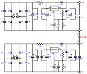
Thanks. Here’s the schematic from the product page. What bit looks strange?
I ordered and built it as +/-18V. Between the ground and V+ it starts around 16V and falls steadily and between ground and V- (the side with the hot diode) it starts around -9V and falls at about the same rate. This is with no linestage connected.
R3 on the V- side also looks a bit heat-damaged
There’s nothing to adjust on the board. I think the voltage is set by one of the resistors
Attachments
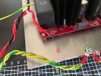
You’ve got the transformer secondaries wrong, and there may be damage on the regulator PCB, as hot anything can be construed as less than ideal…
Pair Black and Red, put them into one of the set of pads marked AC.
Pair Orange and Yellow, put them into the other pads marked AC.
That will give 18VAC into each side of the regulator PCB as it needs to make +/GND/- PSU.
Measure output and see if it’s stable. Also, how are the jumpers connected? Can you show the output side of the board?
Your transformer AC wiring to the PS board appears incorrect.
Black and red should be connected to the AC input on one side of the board and yellow and orange should be connected to the AC input on the other side of the board.
Looks like I was typing when 6L6 posted.
Black and red should be connected to the AC input on one side of the board and yellow and orange should be connected to the AC input on the other side of the board.
Looks like I was typing when 6L6 posted.
Last edited:

What about power supply ground to the amp pcb? There need to be three wires to each board. V-/ GND / V+.
Ok, is it because when I redid it I was thinking i was connecting it as 2 x 18V when it actually needs to be connected as 1 x 36V, with the ground in the middle? Is that where I confused myself, maybe?
What about power supply ground to the amp pcb? There need to be three wires to each board. V-/ GND / V+.
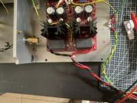
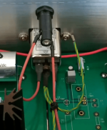
the yellow/green wires are ground from the ac inlet and ground from the transformer and the twisted ones go to the grounds of the ba2018. The ground from the psu was connected to that too before I took the photo
At the output of the PS board, V+ and V- at the centre of the board should be wired together and that becomes Ground to the linestage. V+ at the side edge of the PS board is V+ to the linestage, and V- at the side edge of the PS board is V- to the linestage.
No, what I described is bipolar, and the schematic also shows the bipolar connection. Note that the schematic shows V- and V+, and Ground at the centre where V+ and V- are connected together.
So Ground to the linestage should connected to the centre jumpered outputs and the connection to chassis ground should also be from that point.
So Ground to the linestage should connected to the centre jumpered outputs and the connection to chassis ground should also be from that point.
For bipolar you put in the jumpers and connect to the outside only
Well, no, not exactly… For bipolar you do put in the jumpers and connect as @Ben Mah says, V-, GND, and V+ to the BA2018 PCB.
Please take a few more photos of your preamp so we can see the wiring between the boards.
Ok, is it because when I redid it I was thinking i was connecting it as 2 x 18V when it actually needs to be connected as 1 x 36V, with the ground in the middle? Is that where I confused myself, maybe?
The AC side of the PSU board needs to be connected as 2 x 18V.
Oh ok. Great. I think I copied someone else’s pics at the time but my memory is terrible. I wonder if that’s what was causing the crackling before
@6L6 its all disconnected now. I’ll post a pic once it’s hooked up again before I juice it. I think I’ve probably damaged something on the linestage but I need to head out soon so I won’t be able to troubleshoot it tonight. Thank you both for your help, though
I’ll resolder the PSU properly later and once I’ve got a stable voltage I’ll come back. Is it worth replacing the cooked R3? It seems to measure ok but it looks a bit barbecued. I had the 100R in there so I could use the 10R, I think
Attachments
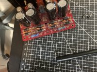
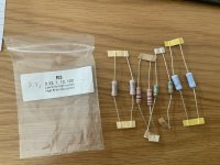
Yes, replacing the cooked resistor(s) with new is a good idea. The 10ohm will do the job very nicely. Do that on both sides to stay symmetrical.
I definitely haven’t got my head around grounding properly yet. The way I had it, the central ground wire was going to what I thought of as the "star ground" although i might be misusing that term, and then the twisted wires went from that to the grounds of each side of the BA2018 pcb.
Is that different to going straight from the jumpered centre V+/V- to the BA2018 ground connections? It seems to me it should be the same. I’m not arguing, just trying to understand.
it’s midnight here. I should sleep.
Is that different to going straight from the jumpered centre V+/V- to the BA2018 ground connections? It seems to me it should be the same. I’m not arguing, just trying to understand.
it’s midnight here. I should sleep.
Grounding confuses everybody. First priority is "don't kill anyone". So I connect a short fat wire from IEC inlet earth to the chassis, using a very secure connection (using lock washers, etc.). If the chassis is made up of multiple separate metal panels screwed together then you should ensure that those all have a low resistance path back to this safety earth, measure... don't assume. So, there's your safety ground.
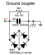
"Circuit ground, what about that?" - that's the grounds on your BA2018 and the PS that powers it. With a separate PS board like you have, I just let that guy serve as the "star ground" for your audio circuits. "But wait, do I connect the chassis / safety ground to this circuit ground or what! And how! I'm so confused!" My current preamp has a ground coupler shown in the attached picture, and I use a CL-60 thermistor in my power amps.
"Circuit ground, what about that?" - that's the grounds on your BA2018 and the PS that powers it. With a separate PS board like you have, I just let that guy serve as the "star ground" for your audio circuits. "But wait, do I connect the chassis / safety ground to this circuit ground or what! And how! I'm so confused!" My current preamp has a ground coupler shown in the attached picture, and I use a CL-60 thermistor in my power amps.
Attachments
RankStranger,
When it comes to star grounds, location is important. The chassis ground is not the location to star ground all grounds.
The IEC power line ground and the power transformer shield ground (green yellow wire) should be connected directly to the chassis ground.
The audio circuit ground is at the power supply ground at the output end of the power supply board, where on your PS board the central V+ and V- are connected together. This is the audio star ground. The power supply ground to the chassis ground is connected to this ground. The ground to the preamp boards are connected to this ground. This is the low noise end of the power supply so the audio ground should be connected here.
The power supply wires to the preamp board should be group in two groups of V+ V- G. Each group of V+ V- G, one for each channel, should be twisted tightly together to keep noise low.
Ok thanks. That makes a bit more sense.
I’ll try to make some time to wire it up today and I’ll post some pics to check before I hit go.
I’ll try to make some time to wire it up today and I’ll post some pics to check before I hit go.
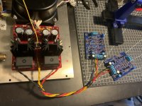
Ok. I’ve replaced R3s and reconnected the transformer to the board in the correct way and I’ve got a stable 17.9V+ on one side and 17.7V- on the other, which I suppose means the PSU board is otherwise undamaged?
I’ve got the ground from the AC inlet and the ground from the transformer connected very securely to the chassis and tested 0.0R resistance to the currently-fitted chassis panels and I’ll confirm for additional panels as I add them back.
the third, thinner yellow wire goes nowhere as yet but I think that joins to my signal ground?
I’ve connected the linestage boards as I understand they should be connected but, reading back I’m wondering if the 6 leads should be split into two where they come together and twisted together as channels, rather than all as one bundle. Would that make a difference?
I haven’t switched it on yet with the BA2018 boards connected so one might yet be busted but I’ll wait for the all-clear before I throw the switch 🙂
Attachments
- Home
- Amplifiers
- Pass Labs
- Wayne's BA 2018 linestage