Then there’s the forum‘s hacks, like zm, who just can’t resist the itch to hack everything😉
Attachments

as has been said—you getting the best of naughty, naughty, naughty me 


BTW: I didn't mention IT... (not by name)
BTW: I didn't mention IT... (not by name)


ZM balanced hack is on post #1,535dunno when, but I already posted proper one
though, will it demand some tweaking in vivo, can't say without actually making it
you have some missing elements there ........ loading resistors in LTP

Hi all,
I really enjoyed making this kit, but could use some advice. Amazingly it all seemed to work from first power up. I've got a decent power supply, nice pot for volume, etc. The issue I have is that it's sounding too open for me. I know it's a transparent linestage, but to my ear what I play is not holding together as a coherent piece of music. I'm hearing details I've not extracted before, but it feels disjointed and maybe jumbled. Like musicians playing in separate rooms. Decent trance is coming across with energy and sounds great, everything else just feels a bit of a mess. It's just not gelling together.
I'm running it at 18v and used the low powered spec components. It's being fed by a Cambridge audio dac and is feeding into the power amp stage of an HK 680 which has been recapped. Speakers are a pair of Q Acoustics 3020. You'll note I'm early in the DIY hobby so gradually working through the chain.
Does anyone have any pointers on what I can do to bring back a bit of musicality? I love the energy and clarity, and I'm not looking for a tube feel, but it's just not hanging together for me. Not abrasive, but fatiguing just the same.
do you have an example of line stage which sound you like, as reference point?
that info could help to devise concept of changes to Wayne's
that info could help to devise concept of changes to Wayne's
I find that a bit odd. My WLS doesn’t sound like that at all.Hi all,
I really enjoyed making this kit, but could use some advice. Amazingly it all seemed to work from first power up. I've got a decent power supply, nice pot for volume, etc. The issue I have is that it's sounding too open for me. I know it's a transparent linestage, but to my ear what I play is not holding together as a coherent piece of music. I'm hearing details I've not extracted before, but it feels disjointed and maybe jumbled. Like musicians playing in separate rooms. Decent trance is coming across with energy and sounds great, everything else just feels a bit of a mess. It's just not gelling together.
I'm running it at 18v and used the low powered spec components. It's being fed by a Cambridge audio dac and is feeding into the power amp stage of an HK 680 which has been recapped. Speakers are a pair of Q Acoustics 3020. You'll note I'm early in the DIY hobby so gradually working through the chain.
Does anyone have any pointers on what I can do to bring back a bit of musicality? I love the energy and clarity, and I'm not looking for a tube feel, but it's just not hanging together for me. Not abrasive, but fatiguing just the same.
my first thought is to give it some time. Mine needed a lot of hours to soften up. Now it is buttery.
Another thought whether all operating points are within spec. Could you provide some pics, and shed some light on how the DC behaviour at the outputs is once adjusted? Does the value jump, or just slowly settle after adjustment?
It is quite possible it will soften up and become more coherent. This was the case for me.
another thought is whether you might have inverted the phase on one channel. That IME produces a palpative soundstage on one side, pulling your attention there. It also feels a bit uncomfortable, disjointed and unnatural to listen to. This can easily be checked by inverting one set of speaker cables.
regards,
Andy
I'm afraid I don't. I'm early in this hobby. I have the B1 and found that a touch too far the other way. Previously I've had a few integrated, and always hunted for more detail.do you have an example of line stage which sound you like, as reference point?
that info could help to devise concept of changes to Wayne's
Thanks Andy. I'm a bit time poor at the moment so I'm going to give it a good run in and also check if I've inverted anything. It does sound like it's just a bit new, and if you found similar in the early hours that sounds like it could be the case. It's probably had about 10 hours so far. I'll give it a few days providing background music and see if it softens up.I find that a bit odd. My WLS doesn’t sound like that at all.
my first thought is to give it some time. Mine needed a lot of hours to soften up. Now it is buttery.
Another thought whether all operating points are within spec. Could you provide some pics, and shed some light on how the DC behaviour at the outputs is once adjusted? Does the value jump, or just slowly settle after adjustment?
It is quite possible it will soften up and become more coherent. This was the case for me.
another thought is whether you might have inverted the phase on one channel. That IME produces a palpative soundstage on one side, pulling your attention there. It also feels a bit uncomfortable, disjointed and unnatural to listen to. This can easily be checked by inverting one set of speaker cables.
regards,
Andy
EDIT: if I were to try an put my finger on it, it feels like there's no sustain on anything. The attack on each note or vocal is good, but it all falls off too quickly leaving a gap in the music. Perhaps this is just how it's meant to sound and I'm hearing music without clutter for the first time. Hope not
Last edited:
Sure all resistors in feedback network according to spec? Did you by any chance adjust gain? I did and it’s character did change, for the worseThanks Andy. I'm a bit time poor at the moment so I'm going to give it a good run in and also check if I've inverted anything. It does sound like it's just a bit new, and if you found similar in the early hours that sounds like it could be the case. It's probably had about 10 hours so far. I'll give it a few days providing background music and see if it softens up.
EDIT: if I were to try an put my finger on it, it feels like there's no sustain on anything. The attack on each note or vocal is good, but it all falls off too quickly leaving a gap in the music. Perhaps this is just how it's meant to sound and I'm hearing music without clutter for the first time. Hope not
I had the same experience. Mine sounded blah in comparison to my other preamps when I first fired it up. It changed after some period of time and became quite lovey sounding. I've built a stupid number of preamps, but this one is my most listened to.my first thought is to give it some time. Mine needed a lot of hours to soften up. Now it is buttery.
I think that’s opposite of correct, I am afraid. Please check the datasheet, you will see it there. There is a slight angle on the fets.0Hi
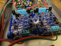
i am wondering if I have got the orientation of the Toshiba transistors correct. could anyone point this out to me?
I have massive dc offset now but no magic smoke.
Q20, Q25 looks right. I wouldn't want any leftover flux residue under/around Q1, Q2, Q3, and Q4. Flux is great for the soldering process but not for operation of these circuits. Isopropyl alcohol, a brush, and some compressed air are your friend here. Repeat process until contamination is completely gone. Is the LED lit? There is a schematic posted at #3303 with some current readings. Output stage should be ~20mA or so on a known good unit. Check the voltage across your part, then calculate current through it with ohm's law... I=E/R. The trimmer pot is very sensitive on these also when you go to set the DC offset.
I second Williams post. The big ones do look correct. But I do not second your solder joints. I see many, many possible cold joints, around several of the small bipolar transistors for example.
that also makes me question the soldering of the small JFETs.
in fact, I would reflow everything that looks sUspiscious. First up: jfets. Without then nothing will work. Try to find the next point on the board after ALL of the jfet legs. Measure resistance with a DMM or use beep mode between the jfet legs and the next point on the pcb (often a resistor leg). That will give you a hint on where to start 🙂 get those right, then move on.
Thanks for the help!I second Williams post. The big ones do look correct. But I do not second your solder joints. I see many, many possible cold joints, around several of the small bipolar transistors for example.
that also makes me question the soldering of the small JFETs.
in fact, I would reflow everything that looks sUspiscious. First up: jfets. Without then nothing will work. Try to find the next point on the board after ALL of the jfet legs. Measure resistance with a DMM or use beep mode between the jfet legs and the next point on the pcb (often a resistor leg). That will give you a hint on where to start 🙂 get those right, then move on.
I was shocked the initial offset was 14dc. Thought it was too much to trim. I am using a less conventional buck boost supply splitter, so that I can use a 24v wall wart.
Cleaned and reflowed the joints as per advice. And trimmed the trimmer to the end and viola 20ma offset.
enjoying how different it sounds from the korgb1. 😬 both are good!
Just to contradict my good ol‘ friend andy,
please post a picture of the other side of the board to confirm the joints. I agree the solder would flow all through the hole to the upper side, but then, looking at the work of other very experienced builders (think 6L6), a joint may be ok even if the solder doesn‘t went through…
OTOH, I always reflow joints from the upperside just to have them looking perfect. And to be sure not to cook those parts, I never solder all legs at once… (first round: all legs on the left, second round: all legs in the center etc.)
Here’s nice (and most probably good) info on solder-joints: https://learn.adafruit.com/adafruit-guide-excellent-soldering/common-problems
😉
Last edited:
Oh, the vanity of the people from the Alps!!Just to contradict my good ol‘ friend andy, please post a picture of the other side of the board to confirm the joints. I agree the solder would flow all through the hole to the upper side, but then, looking at the work of other very experienced builders (think 6L6), a joint may be ok even if the solder doesn‘t went through…
OTOH, I always reflow joints from the upperside just to have them looking perfect. And to be sure not to cook those parts, I never solder all legs at once… (first round: all legs on the left, second round: all legs in the center etc.)
Just wait till it gets some hours on it. Key word: smooooothThanks for the help!
I was shocked the initial offset was 14dc. Thought it was too much to trim. I am using a less conventional buck boost supply splitter, so that I can use a 24v wall wart.
Cleaned and reflowed the joints as per advice. And trimmed the trimmer to the end and viola 20ma offset.
enjoying how different it sounds from the korgb1. 😬 both are good!
- Home
- Amplifiers
- Pass Labs
- Wayne's BA 2018 linestage