I just care of solder point look at side from which I'm soldering
I don't care will solder penetrate on other side of pad
in rare cases ( power resistor in high current path) I care for that and maybe even repeat soldering from opposite side
rare ones, indeed
but, hey, I'm soldering now for almost 4 decades .... and still learning new tricks with damn silly little bugz
My exact strategy with womenI just care of solder point look at side from which I'm soldering
I don't care will solder penetrate on other side of pad
Ha!Oh, the vanity of the people from the Alps!!
(I admit we swiss sometimes appear a bit nonsensical)
Attachments


How many amps you got?My exact strategy with women


I have a question:
My early plans for this preamp have been for a single-ended version to pair with a Pearl but I've been eying an R2R DAC that is supposed to work best with balanced inputs. I've hunted through this thread (rather than read through... it's loooong) and found a number of posts that describe the component differences between the two. I was going to see what it would take to implement a switch that would select between balanced and single-ended inputs -- including double-ganging the attenuator -- but it occurred to me that perhaps the bias adjustment would be different too... and need to be factored in. I didn't see any implementations that provided for this functionality so may it's a dumb question?
Thoughts?
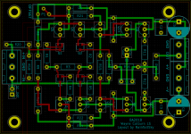
I am in the process of making my board of Wayne linestage in KiCad. Parts more or less settled.
Then everyting will be ready to copy paste to look like one whole board like in the DIYA store.
Is it a good idea to add pinheader jumper for SE mode?
Then everyting will be ready to copy paste to look like one whole board like in the DIYA store.
Is it a good idea to add pinheader jumper for SE mode?
Attachments
I don't see why not. But I personally would be changing R18 and R20 also in addition to the jumper setting, depending on if I were using this with a balanced input, or single ended. Balanced input I would install 10K at R20, and 27K at R18, as Wayne mentions early in the thread.
If I remember correctly you need to change R18 R20 values to make BAL to SE.
Do you need to change those values for just BAL to BAL?
Do you need to change those values for just BAL to BAL?
Oh, I'm not sure on that. I've only used it as a BAL to SE converter, or just normal SE to SE (R18, R20 values per post #1). And I believe the value changes has something to do with preserving CMRR at high frequencies. Someone correct me if I am wrong.
Last edited:
No, but you need two boards per channel.If I remember correctly you need to change R18 R20 values to make BAL to SE.
Do you need to change those values for just BAL to BAL?
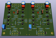
Almost complete.
I have a question about grounds connection for BAL-input BAL-output.
Store board have one grounds connection at the edge of the board, closer to intputs.
Is it because it better should be connected closer to input grounds? Or is it because it just enough?
I have a question about grounds connection for BAL-input BAL-output.
Store board have one grounds connection at the edge of the board, closer to intputs.
Is it because it better should be connected closer to input grounds? Or is it because it just enough?
Attachments
I have a few uPA68H with IDSS 4.3 mA.
Can I use it instead of 2SK209 if I am making my own board?
uPA68H have twice lower Yfs though.
I could not find spice model to sim how it would perform.
By the way I am slowly re read the whole thread and found Patrick's spice files of various simulation on page 35.
Voltage have significant influence on THD. As mentioned before 18V seems like optimal.
Also it seems Q9 Q14 also have significant influence on THD.
Changing them for example to NXP BC327-40 / BC337-40 (different pinout) greatly reduce THD and eleminate 4 order harmonic that otherwise present.
I tryed Bob Cordel's models of BC560C / BC550C and they are amazingly good in Q9 Q14 positions.
But different pinuot than KSC1845 / KSA992.
But different pinuot than KSC1845 / KSA992.
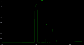
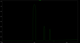
Some simulations to show what I mean.
Picture 1
Original Wayne linestage:
2SK209, KSA992 / KSC1845, Q8 Q10 TTC004B / TTA004B
Total Harmonic Distortion: 0.020234%(0.025464%)
2H: -67.816567dB
3H: -87.853831dB
4Н: -125.89844dB
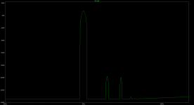
Picture 2
2SK209, KSA992 / KSC1845,Q9 Q14 BC550C BC560C, Q8 Q10 TTC004B / TTA004B
Total Harmonic Distortion: 0.005366%(0.016365%)
2H: -79.508568dB
3H: -91.186182dB
4H: -140.74531dB
Picture 3:
2SK209, KSA992 / KSC1845,Q9 Q14 BC550C BC560C, Q8 Q10 BD140C / BD139C
Total Harmonic Distortion: 0.000679%(0.015476%)
2H: -100.11092dB
3H: -101.21053dB
4H: -133.03007dB
Picture 1
Original Wayne linestage:
2SK209, KSA992 / KSC1845, Q8 Q10 TTC004B / TTA004B
Total Harmonic Distortion: 0.020234%(0.025464%)
2H: -67.816567dB
3H: -87.853831dB
4Н: -125.89844dB
Picture 2
2SK209, KSA992 / KSC1845,Q9 Q14 BC550C BC560C, Q8 Q10 TTC004B / TTA004B
Total Harmonic Distortion: 0.005366%(0.016365%)
2H: -79.508568dB
3H: -91.186182dB
4H: -140.74531dB
Picture 3:
2SK209, KSA992 / KSC1845,Q9 Q14 BC550C BC560C, Q8 Q10 BD140C / BD139C
Total Harmonic Distortion: 0.000679%(0.015476%)
2H: -100.11092dB
3H: -101.21053dB
4H: -133.03007dB
Attachments
It could be those parts need to have their setpoints optimized. If using same settings the bias current won’t be optimal. I don’t think there is intrinsically a reason why 2SK209/KSC1845/KSA992/TTA and TTC are higher distortion. Those are all excellent high performance-capable parts used in some of the best amps.
difference is in models, much lesser in vivoI tryed Bob Cordel's models of BC560C / BC550C and they are amazingly good in Q9 Q14 positions.
But different pinuot than KSC1845 / KSA992.
Somehow simulation is "upset" in KSA992 being at Q14 in particular.
Changing it in to alot of othe built in ltspice BJT models improve THD..
Changing it in to alot of othe built in ltspice BJT models improve THD..
I was using KSC1845 / KSA992 models from files in post #683Somehow simulation is "upset" in KSA992 being at Q14 in particular.
Changing it in to alot of othe built in ltspice BJT models improve THD..
I google at least 2 more models that don't have this anomaly and everything is pretty.
Can anyone recommend good KSC1845 / KSA992 ltspice models?
- Home
- Amplifiers
- Pass Labs
- Wayne's BA 2018 linestage