Hmmm. I have no 680. I do have four pieces of 680K....
Your resistors read "6800", yes?
That's 680ohm and "0" zeros behind it, equaling 680ohm
680K would read "6803", or 680 plus 3 zero
Look at the resistor above Q1 in this photo, and also R14 -
Last edited:
Printing says 6800F. They measure .....whoops, .681 k, guess I didn't catch the ".". My bad. The K threw me, I've been soldering all day.
Russellc
Russellc
It took a while, but I was able to afix all the tiny SMD parts using my new helping hands, bamboo skewer and smallest tip. Magnifying visor of course.
Russellc
Russellc
Built up a Wayne’s linestage test board and works well on the bench but not well when hooked up to my F5 TV2. The power amp blows fuses. Line stage DC offset is good and stays within single digit mVs. Hooked the F5 ac power through a variac and the system plays music till I apply about 75% ac and then distorted sound followed by blown fuse. I suspect RF is getting into the system.


The F5 works perfectly with other preamps.
Are you saying to short the linestage input and check AC and DC on the linestage output with a voltmeter or O scope?
Are you saying to short the linestage input and check AC and DC on the linestage output with a voltmeter or O scope?
Line stage output is less than .008 V DC and less AC with input shorted. The power amp is similar. I do not want to connect the linestage to the power amp again because the fuse will blow and I do not want to damage the power amp. I was hoping on finding something wrong with the way I have the line stage wired before place back into the system. Left and right channels only share a ground at the power supply. I did not connect the left and right
signal ground at the pot or the RCA’s. Is this ok?
signal ground at the pot or the RCA’s. Is this ok?
Maybe your volt meter is inaccurate, also the right channel ground is lifted in the picture you posted. The only thing you can really hurt is speakers with DC. Your problem is very strange. The F5 circuit needs full voltage to stabilize and Class A runs wide open so the input shouldn’t effect the amplifier draw. What Fuse size is recommended for the F5?
The fuse in the power amp is a 4 amp slow blow. I double checked the ground and they are good, must be the optics of the image. Time for me to take a break from this, I’ll investigate further later. Thank you for your help.
Installed the TubeCad Dual/Bipolar LV Reg. It’s really quite nice, slightly quieter then the 317/337 reg installed previously.
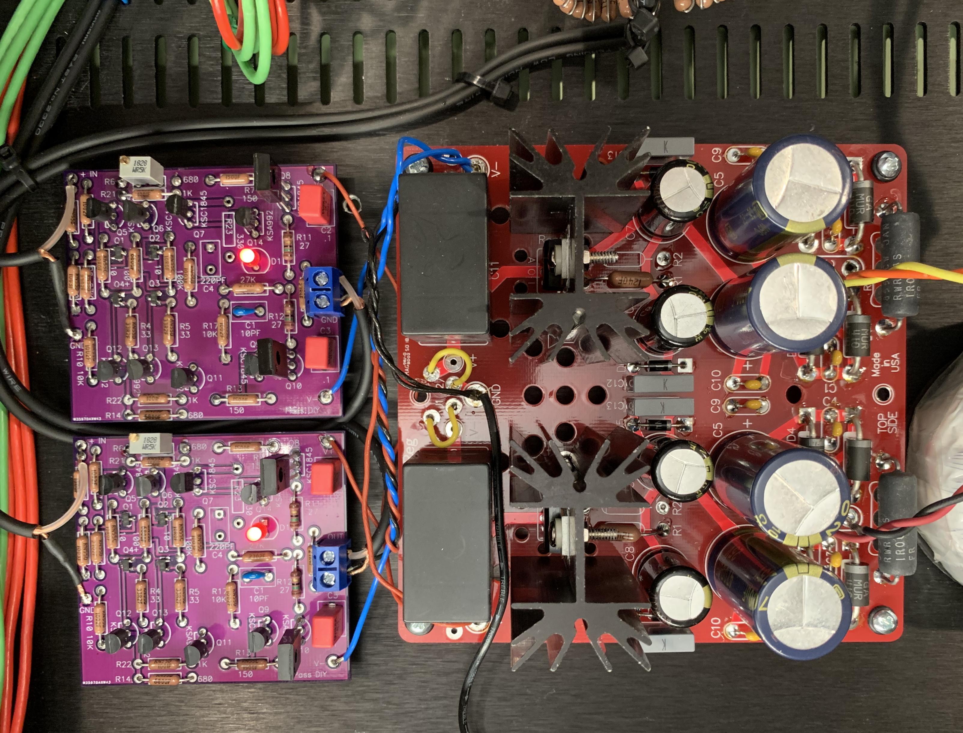
6L6, I PM'd you about wiring, this pic makes it a little more clear as to how the V- and V+ hook up between the power supply (Browski's) and the V- and V+ on the pre boards...Look like two wires go from the power supplies V-, one to each preamp boards V- and two wires from the power supplies V+ one to each of the boards V+
Russellc
Last edited:
Use this photo for reference using the Broskie red PSU
V+ red
V- blue
GND black
Jumper the center of the PSU board, that's ground, take V+ and V- from the outside outputs on the red PSU.
V+ red
V- blue
GND black
Jumper the center of the PSU board, that's ground, take V+ and V- from the outside outputs on the red PSU.
Use this photo for reference using the Broskie red PSU
V+ red
V- blue
GND black
Jumper the center of the PSU board, that's ground, take V+ and V- from the outside outputs on the red PSU.
Very clear now. I was about to use the V- and V+ between the large blacl film caps. As to the center ground, I see one going to chassis, then two thin black twisted wires I presume one of each to the preamp board ground, right? Great hi res pic BTW!
Russellc
Yes. If you click into the photo and make it big, you can barely see a black wire in the terminal block under the coax braid. Hard to see, but it's there on both boards. 🙂
Thanks for the hook up hints, much appreciated. Dont want to smoke this thing....it was inexpensive, but those SMT critters were something else. Too tired tonight, will attach preamp boards tomorrow and set offset. Attach input RCAs, Volume pot and output RCAs and try it out,
Russellc
Russellc
Hi Russellc,
That Tubecad PS looks pretty interesting.
The only real issue I had building this preamp (aside from a humming transformer)
was one of the jfets acting up because of flux residue around it. So I recommend
checking that before power up.
Please let us know how you like this preamp.
Cheers,
Dennis
That Tubecad PS looks pretty interesting.
The only real issue I had building this preamp (aside from a humming transformer)
was one of the jfets acting up because of flux residue around it. So I recommend
checking that before power up.
Please let us know how you like this preamp.
Cheers,
Dennis
- Home
- Amplifiers
- Pass Labs
- Wayne's BA 2018 linestage