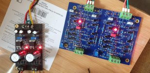
Another one lives.!
Finally managed to power up yesterday. Using a Chinese opamp buffered thing for now set to 15v.
Leds came straight on so that was reassuring. Left it for a while and checked for magic smoke/heat. All seems well.
Measured the offsets and they were both initially 0.5v but got one easily down to a steady pretty much 0v. At most it reads 0.005v so very please with that channel. The other one was much trickier. Just looking at the VR and the reading would shoot between +/- 20mv. Managed a fairly solid 0.010 or so.
Will hopefully get to hear it today.
Many thanks again to Andynor for the kit.
Attachments
Last edited:
Thanks Keith
Do you have a Ba18 Keith and have an opinion on the sound differences? The DCG3 was the only preamp I thought I'd ever need....but alas....this hobby!
Do you have a Ba18 Keith and have an opinion on the sound differences? The DCG3 was the only preamp I thought I'd ever need....but alas....this hobby!
Another one lives.!
Finally managed to power up yesterday. Using a Chinese opamp buffered thing for now set to 15v.
Leds came straight on so that was reassuring. Left it for a while and checked for magic smoke/heat. All seems well.
Measured the offsets and they were both initially 0.5v but got one easily down to a steady pretty much 0v. At most it reads 0.005v so very please with that channel. The other one was much trickier. Just looking at the VR and the reading would shoot between +/- 20mv. Managed a fairly solid 0.010 or so.
Will hopefully get to hear it today.
Many thanks again to Andynor for the kit.
Congrats, James! Glad to see the parts having come to life in circuit. And I myself am very excited about the parcel you have sent me, what exciting stuff is in there I am yet to see 😀
Wrt the offset drift, as long as your listening test is quiet on that chan, I would preliminary conclude the JFETs are OK, and proceed with measuring the voltage drop across R1 and R2. They should show stabily about 3mA/30-ish mV drop if I remember correctly. Any instability there will amplify downstream causing offset drift. Though 20mV drift is probably OK, I believe some have experienced more than that - and I more on my first go.
If there is any instability in the CCS, that is not there on the other chan, I would recommend you carefully reflow the JFET legs and then clean again. I don’t see the inputs shorted, that might help as well. Make a wired B shorting everything to center of the euroblock.
PS: If you cleaned with isoprop before testing the first time, first try again after a while before doing anything else. My circuit went ape when the JFETs had hidden isoprop under them
 I was too impatient to wait for it to dry properly.
 So basically, if there is drift the first likely culprit is the CCS/JFETs. If stable there, issue is downstream where parts are bigger and the fix might be easier.
Or you could prolly live with it 🙂
Excited to hear what you think of it’s sound!
Regards,
Andy
Last edited:
Thanks for the input Andy. I wouldn't say it has instability, just that one channel was harder to nail down the offset. Once I leave the trim pots alone the offset measurements are stable. It was populated some time ago and thoroughly cleaned. It will be dry!
Hope the parcel arrives soon!
Hope the parcel arrives soon!
I see. Sorry, James, I misunderstood then. The pots can be quite sensitive 😀 Build looks smooth!!
Thanks Keith
Do you have a Ba18 Keith and have an opinion on the sound differences? The DCG3 was the only preamp I thought I'd ever need....but alas....this hobby!
I am in the process of assembling one so as yet cannot comment. As you say this hobby it gets a hold on you😀
When the balanced B1 korg preamp was used, the B&W speakers had a wide and deep soundstage. I've had friends who heard the system say they heard instruments playing next to them. When I switched to the BA2018 preamp, that 3D soundstage was missing with the B&W speakers. The sound clarity was exceptional, yet it lacked the depth I so enjoyed.
The Lowthers changed the depth issue I had with the B&Ws, not sure why the B&Ws didn't like the BA2018.
I used Nichicon green capacitors because I remember reading some where that Wayne preferred them. Not sure if it helps or hurts.
I do enjoy the BA2018 with the Aleph J, I am hearing a sound from the system that I enjoy immensely. The UFSP phono section adds even more to the sound quality.
Out of curiosity, when the "3-D soundstage went missing," did you happen to try reversing the polarity at the speaker hookups and try it?
Russellc
Out of curiosity, when the "3-D soundstage went missing," did you happen to try reversing the polarity at the speaker hookups and try it?
Russellc
The BA2018 I built is Balanced with two boards, this cancels the H2 from what I've read. I didn't swap polarity using the B&W's, however they are back in the main system do to a Lowther voice coil failure (under warranty), my second in a row. So I have to break in the new driver, Lowther sent it DHL no questions asked, great customer service!.
I will try to swap speaker polarity when I put the BA2018 back in the system, it is out to measure distortion. I'm building the PASS H2 V2 generator, so that the BA2018 line stage is back to H2 primary.
Hello Gang, I’ve finally getting back around to getting hopefully getting Wayne’s Linestage together and hopefully operational. I’m having a major brain fart and perhaps you guys will have a viable solution. I’m planning on using the Muses VCM volume module along with the Muses MCL display. I need a connector that will plug into the header on the VCM that’s will go from a male connector to wire where they can land on the psu, Linestage board and lastly to the RCA in and out. I hope something is available. If not perhaps a suggestion of how to make all this happen. I’ve attached some pics. Thank you in advance. Joe
Attachments
In the user manual the connector is described as:
A universal connector J3 combines all audio, power and control connection points. J3 is arranged as a 16-pin dual row 0.100”x0.100” PCB pattern that can accept a standard straight or right angle header.
Crimped pin connector inserted into female header Blocked
On mine Project I did not use the header and instead soldered wires between pcb hole pads and other circuit pcbs directly with less connection points of failure.
@Dane, thank you for the reply. So was your VCM was sent without the header connector already soldered in? This is how I received mine already soldered to the board. I’m thinking it would be a tedious surgery to remove it at this point?
Here's the first search that came up on Amazon. I use them for all sorts of things.
https://www.amazon.com/Elegoo-EL-CP...3&sr=1-1-f0029781-b79b-4b60-9cb0-eeda4dea34d6
https://www.amazon.com/Elegoo-EL-CP...3&sr=1-1-f0029781-b79b-4b60-9cb0-eeda4dea34d6
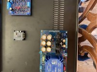
So I mocked everything up so that I could test it all. Pretty much patched everything together with cat5 wire just to see if It would blow up... It didn't. I was able to set the offset to near 0 volts on both sides. I am getting noise on one channel and low volume on the other... Ugh. I think it may be the SMD jfets. I am on my 2nd round of them on the noisy side, 1st set on the low volume side.
One of the little SMDs is microphonic (Q21 the noisy channel). Is there an easy way to check them to make sure that they are all properly operational? I am going to go through the schematic and make sure that everything is in it's correct location.
One of the little SMDs is microphonic (Q21 the noisy channel). Is there an easy way to check them to make sure that they are all properly operational? I am going to go through the schematic and make sure that everything is in it's correct location.
Unbalanced in to balanced boards
Hi all,
I'm building a BA2018 linestage in fully balanced configuration, using two boards. I've found the info on the thread for how to connect them for balanced operation. However I can't seem to locate any info on how to handle an RCA input from CD and phono (I'll be using a fully balanced DAC but would prefer to stick with current unbalanced CD player and phono stage). How do you connect to the boards? Is there a simple method, or do I need to use an unbalanced to balanced converter in this instance?
I can't seem to find anything on any of the threads. Any help gratefully received!
Thanks in advance 🙂
So I mocked everything up so that I could test it all. Pretty much patched everything together with cat5 wire just to see if It would blow up... It didn't. I was able to set the offset to near 0 volts on both sides. I am getting noise on one channel and low volume on the other... Ugh. I think it may be the SMD jfets. I am on my 2nd round of them on the noisy side, 1st set on the low volume side.
One of the little SMDs is microphonic (Q21 the noisy channel). Is there an easy way to check them to make sure that they are all properly operational? I am going to go through the schematic and make sure that everything is in it's correct location.
Sorry to hear that. I was in the same sit. I will tell you right away that I ended up building a new circuit, when I discovered PCB damage post replacing JFETs. Very sensitive in that part of the circuit, doesn’t take much to cause instability.
1: Did you measure every resistor before mounting/ie sure they are all correct?
2: Pics of both chans helpful for anyone wanting to help
3: Measurements of voltage drop ACROSS all 10R resistors in the CCS/in the traces from the JFETs on both chans. Observe drop and note any drift, and share here. Also, post the drift in output offset in mV for both chans. Let it stabilize after startup first, should happen within 2-5 minutes.
4: Please confirm you have checked the PCB under the teplqced JFETs for scratches, and that everything - especially JFET legs ate properly cleaned. Just to rule out a few things.
5: If you have diode/beep mode on your DMM, the following might prove fruitful iot identify problem areas in the CCS:
- Put one probe on the JFET leg, the other to the next solder island on the PCB. Following the PCB traces with your eyes will enable you to find these points (some are a bit hard to find/defy logic initially but are then very logic once you find them. Repeat for all legs on all JFETs. Resistance should be very, very low. If high between two points, there is an possibly an issue there. Others have solved such issues by reflowing. With flux.
Regards,
Andy
Last edited:
- Home
- Amplifiers
- Pass Labs
- Wayne's BA 2018 linestage