If I wanted to use the amp in a variety of systems which input sensitivity resisters should I use? 1v or 2v
I find the 2V setting works best across multiple applications. But that could be because I don't listen all that loud - I'm normally not using any more than 10W. If you love to play it loud, go for the 1V.
Im a low level listener too. All my drivers are at least 95dB/W/m so my biggest amps are going to be F5, F4, Mofo and this one. All hovering around 25w but listening around 5w
Ill get soldering. Cheers Richard
Ill get soldering. Cheers Richard
Different transformer
Speaking about input sensitivity reminded me we recently got a few boards made with a different input transformer. Its considerably bigger : EE35 vs EE25 for the standard one.
The thinking behind the larger trafo is to give more flexibility over input sensitivity. Why do we stick to such a low voltage as 2VRMS when most circuits being based on opamps can easily output 8VRMS even unbalanced? The EE25 trafo cannot handle such high voltage signals because the wire for the primary gets to be too thin and difficult to wind without breaking.
Enter the EE35 trafo - with a much bigger winding window it can easily handle 8VRMS and likely even higher.
The main reason for wanting higher voltage capability is to get higher SNRs out of the analog stages of DACs which are typically limited by opamp noise if JFET or CMOS opamps are used.
Attachments
A customer has asked me if I can provide further technical details about the input transformer so that a trafo manufacturer can provide a souped-up version to take this design to the next level. He has suggested Cinemag as the likely manufacturer.
I went over to Cinemag's website - here : Audio Transformers By Cinemag Inc.
On that page there is already one off-the-shelf trafo which will likely work fine, that's CM-2560, billed as a consumer to pro interface with an operating level of +8dBV. Its likely that this level is on the consumer side so the pro side will be considerably higher.
The turns ratio on my original EE25 is 7.5:1 step down. So for 2V on the primary the secondary sees 267mV. The TDA8932 provides a gain of 63.1X so 267mV is amplified to 16.8V. Except that results in slight clipping as the supply voltage isn't high enough.
The Cinemag trafo doesn't give the step down ratio but we can calculate it from the impedances (600ohm, 14.5k). The turns ratio is the square root of the ratio of the two impedances. Which works out at 4.9:1 so this will give 3.7dB more gain.
If a custom transformer is spec'd then we'd reduce the impedance of the 600ohm winding to lose 3.7dB of excess gain - this gives a new impedance of 250ohm. The voltage handling doesn't need to be anywhere near the +8dBV spec so ISTM Cinemag could just reduce the number of turns on the consumer side to reach 250ohm impedance.
In my EE25 trafo I didn't take any measures to try to reduce the leakage inductance, whereas trafo manufacturers will typically interleave primary and secondaries to get lower leakage which turns into a higher bandwidth. In my design I utilize the leakage inductance to create a low-pass filter in conjunction with some Rs and Cs. Given that its hard to duplicate the leakage inductance of a particular design when specifying a custom trafo it's likely the best route to minimize the leakage and then adjust the Rs and Cs on the PCB to compensate for that.
The other wound components are the output inductors - these are much more simple. We need to be able to handle 4A peak current without saturating and we'd also like the AC losses at 320kHz (the amp switching frequency) to be as low as possible. Normally output inductors are gapped ferrite to achieve low enough losses, but air-core could be even lower loss in theory. However air-core output inductors will be much more bulky and they're going to have higher leakage of flux so will need careful placement not to interfere with other nodes of the amp.
Hi Richard,
Really enjoying these boards, great info.
Are the CM-2560 pinouts a direct drop in replacement or is there a drawing to show pinouts of your pinouts?
From the Lundahl rage is there any that fit the task, perhaps LL1952?https://www.lundahltransformers.com/wp-content/uploads/datasheets/1952.pdf
Cheers
From the pdf on their site, the CM-2560 is in a cylindrical container and has two rows of pins separated by 17.8mm whereas EE25 has ~15mm between rows. So not a direct drop-in even though the pin spacing looks the same (5.08mm). Their mech drawing doesn't show winding allocation to pins - only the wired version shows wire colours vs schematic.
I'll take a look at Lundhal.
The Lundhal you linked doesn't look like it could be adapted to work because the consumer level winding isn't centre-tapped.
I'll take a look at Lundhal.
The Lundhal you linked doesn't look like it could be adapted to work because the consumer level winding isn't centre-tapped.
Last edited:
This Lundhal is better suited, though not quite ideal because the step-down ratio is only 4:1, so you'd end up with about a 1V input sensitivity (rather than ~2V with my EE25). You need to use it backwards (as step-down) compared to the way they describe it (as a step-up).
https://www.lundahltransformers.com/wp-content/uploads/datasheets/1922.pdf
https://www.lundahltransformers.com/wp-content/uploads/datasheets/1922.pdf
Thanks for the detailed responses Richard, very much appreciated, I think I will go with the CM-2560 and report back. It may well be that yours are better suited, but the chase is half the fun, is it not : )
Have a great day to all
Have a great day to all
If you're wanting more options, these look like they'll fit the bill : Page Not Found - Aliexpress.com
Quite a bit cheaper than the Western brands.
Quite a bit cheaper than the Western brands.
Hi Richard,
I just received my kit. Looks great with most of the small SMT parts already installed. What is the latest stuffing diagram or schematic I should be working from to build this?
Thank you.

I just received my kit. Looks great with most of the small SMT parts already installed. What is the latest stuffing diagram or schematic I should be working from to build this?
Thank you.
Last edited:
Hi X,
Apologies that we omitted to update the original soldering guide when we arranged for most of the parts to be pre-fitted at JLC. The original one is here https://www.diyaudio.com/community/...8932-25w-8r-mono-amp-kits.359193/post-6330196 and I'll attach the updated one to this post.
Good luck with the build!
Attachments

xrk, did you build and test this amp yet?Hi Richard,
I just received my kit. Looks great with most of the small SMT parts already installed. What is the latest stuffing diagram or schematic I should be working from to build this?
Thank you.
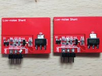
New shunt PCB as of last month - we've tweaked the layout and now the shunt PCBs mount on the mainboard at 180degrees relative to the old shunts. There is no electrical difference though, just slightly re-positioned components. How to know if you have a new shunt? - it'll have 'Low-noise shunt' on the silkscreen. The old shunts didn't announce themselves.
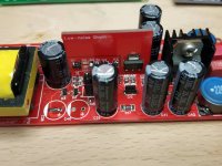
The second pic shows the new orientation - the height of the shunt board isn't representative as that's my test board in the shot, complete with socket. Pin1 (GND) is to the left.
The second pic shows the new orientation - the height of the shunt board isn't representative as that's my test board in the shot, complete with socket. Pin1 (GND) is to the left.
Attachments

- Home
- Amplifiers
- Class D
- Transformer input TDA8932 mono amp