Are the new SLB version for the single railed pcb availabled in your webshop?
Please inform how to adjust the trimpot on the SLB?
Please inform how to adjust the trimpot on the SLB?
X, thanks for the reply. Having a hard time visualizing a single rail psu being used for 2 channels. Single rail to me means 1 channel or 1 pcb in the case of ACA. So for 2 ACA pcbs, why not a dual rail. Help with understanding.
MM
MM
@kokanee:
Single rail means single positive voltage output.
Dual rails means positive and negative output.
You could use dual single rails for dual ACA monoblocks. However if ACA is in single chassis, a single rail SLB can easily handle current for both channels as it can do 5 A continuous.
@myl: In the shop, choose the single rail variation. The trim pot gives about only 1v of adjustment. It’s really not needed in retrospect as we should have just set it at about the midpoint with a resistor. It’s to allow adjustment of the output to make sure ripple is minimized. You need an O-scope to do that.
If you are looking for some Dual rail SLB pcb, please check the Swapp Meet forum under thread Class A pcb's. Good prices. X gave me permission to post here.
Regards
Regards
GB3 Interest List (I need at least 8 boards to make a critical mass).
Name // No. of Boardsets // Country
Gregetzoff 1 boardset USA
redjr 1 boardset USA
Name // No. of Boardsets // Country
Gregetzoff 1 boardset USA
redjr 1 boardset USA
Which GB are we talking about? This is the SLB thread - I think we were talking about the Yarra preamp main board?
Ok, i am lost.
Received my board today and thought a BOM would be included. this would be for the dual rail version.
Received my board today and thought a BOM would be included. this would be for the dual rail version.
Ok, i am lost.
Received my board today and thought a BOM would be included. this would be for the dual rail version.
The Schematic and BOM are in the first post of this thread. It’s a little hard to see with the link in the word “here”. You’ll see it.
There’s also a link to a shared mouser project somewhere in this thread.
Last edited:
Please note that these are v1.2 boards and no longer accept the 90 deg Molex Minifit plugs. They are the vertical ones now. This was to make the board lower profile.
The PCB 4-pin connector jack is actually made by Wurth (part no. 64900421122), compatible with Molex Minifit. 2x2 pins:
64900421122 Wurth Elektronik | Mouser
The PCB 4-pin connector jack is actually made by Wurth (part no. 64900421122), compatible with Molex Minifit. 2x2 pins:
64900421122 Wurth Elektronik | Mouser
Last edited:
Please note that these are Gen 2 boards and no longer accept the 90 deg Molex Minifit plugs. They are the vertical ones now. This was to make the board lower profile.
Just like to assure people that the vertical Molex sockets work fine on Gen 1 boards. 🙂
That's what I used, as I am mounting my SLB boards vertically - so couldn't have the wires coming off sideways to the boards.
Andy
Hi Andy,
Do you have that Molex vertical socket part number handy?
Sure, X ... it's Molex 39-28-1043.
Andy
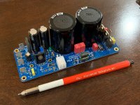
I don't think I ever posted this, but a while back, I tested out the SLB single rail at 30v and 3.75A using a big 8ohm wirewound dummy load. It showed excellent performance with sub 1mV rms ripple. This is perfect for a single rail Class A amp like the MOFO.
SLB SR fully assembled:

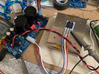
Test setup:

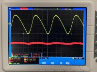
Measured ripple upstream of the ripple eating BJT and after it:

SLB SR fully assembled:
Test setup:
Measured ripple upstream of the ripple eating BJT and after it:
Attachments
A new generation of SLB’s, now in green!
Rotating the trimpot 90° and changing to a vertical mounted Molex Minifit header are subtle but very welcomed revisions.
Thanks X and Jhofland 🙂
Vunce,
I don't see RV2's trimpot rotated on the recent green silkscreened dual rail SLB's...do you?
Best,
Anand.
Regarding the trimpot, it wasn't rotated. Just moved away from the heatsink a bit so there wouldn't be an interference.
Has anyone had trouble getting the ground Faston tabs soldered properly? I know that they conduct a bit of heat out and it might be hard for solder to fully melt and flow. So if you are having issues, please try to use a bigger (higher wattage) iron, use a big fat chisel tip, use good name brand leaded rosin core solder, set the iron to 400C. Hold the chisel blade so that it touches the flat of the spade terminal and the board solder pads. Slowly add solder so it melts and flows. Hold it for about count of 10.
If this still doesn’t work, preheat the area on the board with a hot air gun.
If this still doesn’t work, preheat the area on the board with a hot air gun.
Has anyone had trouble getting the ground Faston tabs soldered properly? I know that they conduct a bit of heat out and it might be hard for solder to fully melt and flow. So if you are having issues, please try to use a bigger (higher wattage) iron, use a big fat chisel tip, use good name brand leaded rosin core solder, set the iron to 400C. Hold the chisel blade so that it touches the flat of the spade terminal and the board solder pads. Slowly add solder so it melts and flows. Hold it for about count of 10.
No, I've not had any problems like that, X. (But I do have a non temp-controlled soldering aron with a 6mm wide chisel tip. 🙂 )
The problem I do keep having 😡 is that, as the PCB is upside down for the soldering, the solder travels down to the end of the spade ... making it hard to get the female connector on. 🙁
If this still doesn’t work, preheat the area on the board with a hot air gun.
Great tip, X! 🙂
I will use my new air soldering gun for this, at the very least! 😀
Andy
This is one of the few parts that I solder it from the top side first. No dripping problem - maybe that is the trick to applying a lot of heat?
- Home
- Group Buys
- The SLB (Smooth Like Butter) Active Rect/CRC/Cap Mx Class A Power Supply GB