Hi folks, I should state that the purpose of the pot was to allow some adjustment of the voltage drop to obtain suitable ripple rejection. Typically that will be about 3v. You really can’t check for that unless you have an Oscope. But 3v is pretty good. I would not go in and change the circuit as it has been tested and verified to be oscillation free. The CFP topology is very sensitive to changes that could set it into oscillation.
In hindsight, we should have just installed a fixed value at the pot to give about 3v drop which seems to handle even large 4.5A of current.
In hindsight, we should have just installed a fixed value at the pot to give about 3v drop which seems to handle even large 4.5A of current.
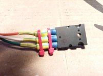
Hey people... have a little tip for you for the flying leads. You can see the way X did them and it's fine, but a little change can make the leads much more stable. The way they are lends to them getting bend very easy.
Take a butt connector sized to accept the lead and the wire you want to use. Cut the insulation back to the actual butt connector on one side. Th other side leave alone. The side you cut back will be the solder connection side. Slide the connector over the lead on Q10 or Q12. 1943 or 5200. Now you should have Q10 leads sticking slightly out the end where you trimmed back the isolation, stuff your wire (don't forget your properly sized shrink tube) in there (tin it if ya like) and solder it in place. Repeat for all leads.
Make sure when you set the completed package on a flat surface the zip tie doesn't prevent it from sitting flat on sink surface. If it does, carefully give them a slight bend until the no longer obstruct proper sinking.
For the next step you will be adding two small zip ties spaced apart a bit, see picture. Now when the zip ties are in place, it makes the leads on Q much more rigid. You could even remove the insulation from both ends and trim the leads back a bit....
Attachments
Last edited:
So you know, it gets darn hot there on those leads. But that’s for the main amp running 150w in the MOSFET. Not sure how the plastic of that butt crimped insulator will fare at higher temperatures. It’s worth noting that I use extremely soft and flexible silicone jacketed RC car wiring for motor/batteries. The soft wires reduce mechanical stress on the leads. Also, using the snubber boards to relieve stress also makes sense.
So you know, it gets darn hot there on those leads. But that’s for the main amp running 150w in the MOSFET. Not sure how the plastic of that butt crimped insulator will fare at higher temperatures. It’s worth noting that I use extremely soft and flexible silicone jacketed RC car wiring for motor/batteries. The soft wires reduce mechanical stress on the leads. Also, using the snubber boards to relieve stress also makes sense.
This is the SLB thread, so it wasn't meant for the others as I used the snubbers, but they would work fine there too. Most of the ones out there are rated around 100C, if the **** get's that hot you have other issues. 😎
It's something to keep in mind for sure.....
Hi folks, I should state that the purpose of the pot was to allow some adjustment of the voltage drop to obtain suitable ripple rejection. Typically that will be about 3v.
I get a max of about 2.5v difference in the output, winding the pot fully up to fully down.
I would not go in and change the circuit as it has been tested and verified to be oscillation free. The CFP topology is very sensitive to changes that could set it into oscillation.
Sure but with the pot, you've allowed a resistance range of 75 - 275 ohms. Do you think I really have to change the 121 ohm res I substituted for the 75 ohm res ... back to 75 ohms? (Given the range is now 121 - 321 ohms.)
In hindsight, we should have just installed a fixed value at the pot to give about 3v drop which seems to handle even large 4.5A of current.
Haha - yes! Next time! 🙂
Andy
Guys, how do you stop the pin sockets in the Molex header from riding upwards as you push it down onto the part of the connector which is soldered to the PCB - which has the pins?
This afternoon I've been attaching pins to the wires coming from the 2SA1943 & 2SC5200 transistors - and then:
* plugging the wires into the Molex wire headers
* then plugging the Molex headers onto each SLB board
* attaching the relevant power transformer
* then attaching the load res to each DC output, in turn, and
* switching on.
Then I've been adjusting RV1/RV2 so that the DC output - under load - is matched (near enough as I can get it) for the +ve & -ve outputs.
Two SLBs worked fine ... also the +ve DC output of the 3rd. But doing the -ve output of the 3rd ... the magic smoke came out of R15. 😡
Looking at it, it appears that the Base pin-socket slid up inside the Molex housing - and instead of sliding over the pin in the base (and making tight contact like the others had done) ... simply lifted ... and disconnected.
So:
Q1: how can I make sure these damn pins stay in place, in the Molex housing, when you push the two parts of the connector together?
Q2: Will Q11 be blown - or only the resistor? How can I tell if the BD140 is OK ... or not.
Thanks,
Andy
Andy,
You must have not installed the pins properly. There is a “U” shaped cross section profile with barb on one side. Look at the plastic shell and notice the U shape. It will lock when done properly and not slip out.
If you have a bad connection to the transistor, the R14/15 68R 1/2w resistor takes full load and burns like a fuse. Replace the resistor and all is well again.
Last edited:
Hi Andy,
There is an audible “snap” sound when the pin assembly is pushed into the plastic housing. Once it’s snapped into position, the pins will not back-out when the Molex connector is attached to the pcb header.
There is an audible “snap” sound when the pin assembly is pushed into the plastic housing. Once it’s snapped into position, the pins will not back-out when the Molex connector is attached to the pcb header.
Thanks, guys,
I have removed the offending pin-socket and will closely look for the barb and the U-profile, and listen for the 'snap' when I re-insert the pin-socket.
btw, the pin-socket shape is distorted after I've used the crimping tool - so it's difficult to see the correct orientation in the header socket. 🙁
Luckily, I have a bunch of Holco 68R1 reses to replace the burnt res. 🙂
Andy
Thanks, guys,
I have removed the offending pin-socket and will closely look for the barb and the U-profile, and listen for the 'snap' when I re-insert the pin-socket.
btw, the pin-socket shape is distorted after I've used the crimping tool - so it's difficult to see the correct orientation in the header socket. 🙁
Luckily, I have a bunch of Holco 68R1 reses to replace the burnt res. 🙂
Andy
As a sanity check, once it snaps in place, and not all of them seem to make the snapping sound btw, I always pull back on the wire to make sure it has locked in. Also, I don't trust those things as the wire I used seemed to be one size larger than optimal, so I crimp then solder all of mine.You have to use the solder sparingly, or the pin won't fit in the connector. I just feel more comfortable knowing the solder is there.
I put one in the wrong way as well. Once inserted the wrong way those "barbs" on the pin itself seem to flatten out. Just bend them back out with a small flat head screwdriver. When re-inserted with the correct orientation they should CLICK into place and be permanent.
Last edited:
I put one in the wrong way as well. Once inserted the wrong way those "barbs" on the pin itself seem to flatten out. Just bend them back out with a small flat head screwdriver. When re-inserted with the correct orientation they should CLICK into place and be permanent.
Yup, I use a needle to open them back up, they don't need to be open real far.
Also, if you need to remove one that IS seated correctly, you can take two needles, one on either side, use a needle-nose to push them into the locking area, hold the connector firmly and pull the wire firmly to release it from the connector. If done right, you just need to expand the locks again and you can reinsert. I had to do this when I hosed the wiring once, or twice. 😱
Hi Folks,
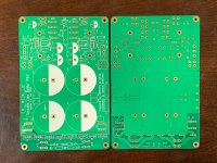
The new boards just arrived. Hopefully, I will be shipping them out this weekend. Thanks for yiour patience. They are green solder mask but still 2mm thick, 2oz copper, and ENIG finish.

Btw, I am about to build up a new verification build of a universal preamp PSU with what has got to be the world's smallest LT4320 active bridge, a CRCLC, and TPS7Axx LDO regulators on the final output.
Here are the new LT4320 bridges (13mm x 10.5mm ea):
More info on the new Yarra PSU with LDO regulators here:
The YARRA Preamplifier/HPA for Melbourne DB Group Buy
The new boards just arrived. Hopefully, I will be shipping them out this weekend. Thanks for yiour patience. They are green solder mask but still 2mm thick, 2oz copper, and ENIG finish.
Btw, I am about to build up a new verification build of a universal preamp PSU with what has got to be the world's smallest LT4320 active bridge, a CRCLC, and TPS7Axx LDO regulators on the final output.
Here are the new LT4320 bridges (13mm x 10.5mm ea):
More info on the new Yarra PSU with LDO regulators here:
The YARRA Preamplifier/HPA for Melbourne DB Group Buy
Attachments
I just received a request for starting up a GB3 list for the Yarra main board set (with original cap Mx PSU). Note that the cap Mx PSU is still an excellent suppy and very low noise and capable of more current flow than the 1A that the newer LDO version will be limited to. If you do not need a fixed/regulated voltage, but simply a quiet and low ripple suppy, the original one still works and has the ability to go above +/-32v, possibly needed in some designs for high power outut 0dB gain power amps.
GB3 Interest List (I need at least 8 boards to make a critical mass).
Name // No. of Boardsets // Country
Gregetzoff 1 boardset USA
GB3 Interest List (I need at least 8 boards to make a critical mass).
Name // No. of Boardsets // Country
Gregetzoff 1 boardset USA
Thanks, guys:
* have inserted a fresh 68R1 res and checked that I read a value between pins 1 & 3 of Q12 (for some reason, this value is not 68R1?).
* have widened the barbs on the pin socket.
* inserted the pin-socket and tried to pull the wire back out (couldn't! 🙂 ).
* plugged in Q10 & Q12 and attached the power traffo
* then switched on!
NP. 🙂
JT, previously - when I didn't have a crimper - when attaching spade terminal sockets to wires, I would crimp with my thin-nosed pliers and then apply solder, to make a nicely permanent connection.
But my new crimper does a great job on these Molex pin-sockets ... and it seems it would be easy to use too much solder - preventing the pin-socket from being inserted into the Molex header - so I think I will stick to crimping.
Thanks for everyone's help.
Andy
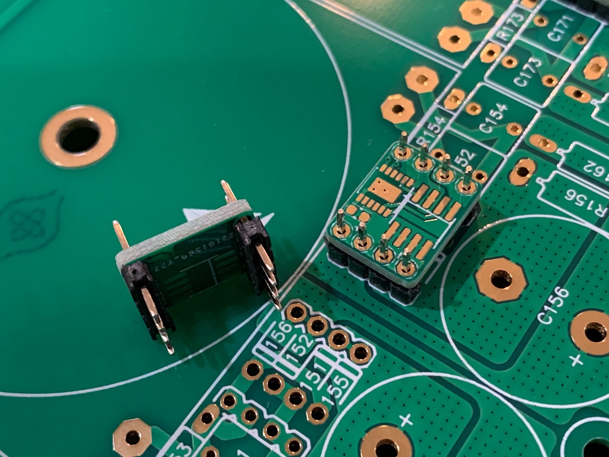
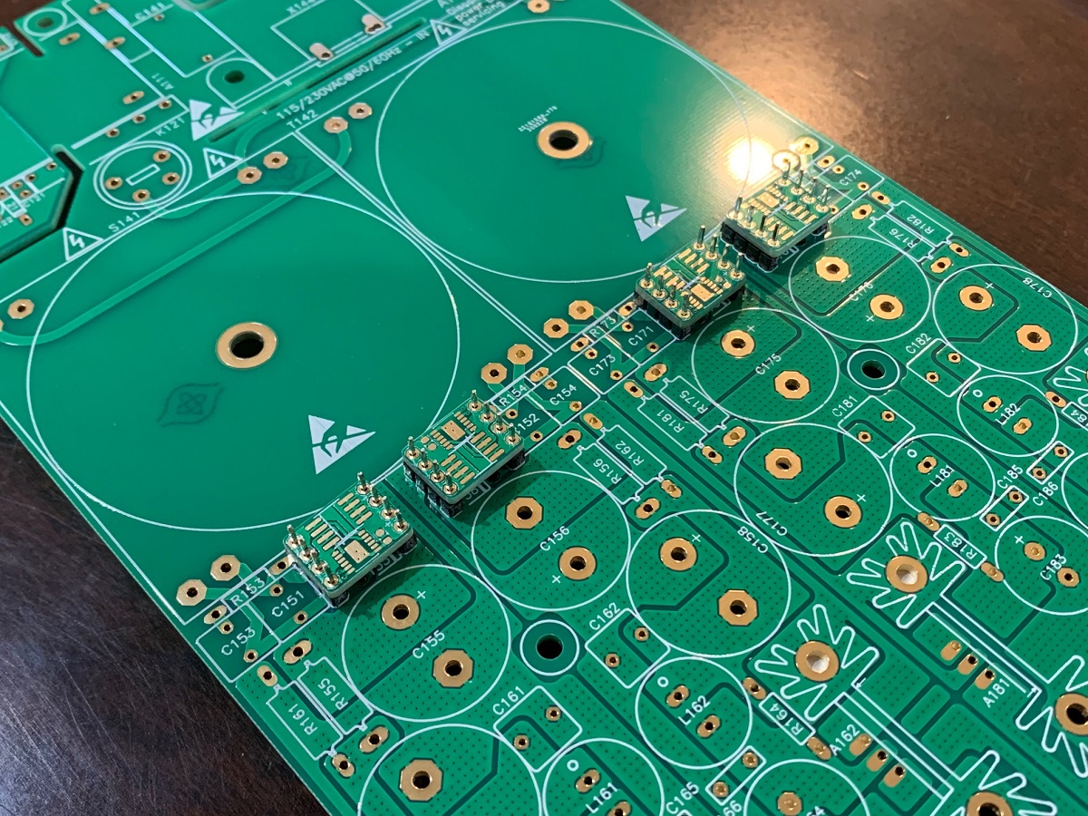
A new generation of SLB’s, now in green!
Rotating the trimpot 90° and changing to a vertical mounted Molex Minifit header are subtle but very welcomed revisions.
Thanks X and Jhofland 🙂
Rotating the trimpot 90° and changing to a vertical mounted Molex Minifit header are subtle but very welcomed revisions.
Thanks X and Jhofland 🙂
Hi X,
Starting to get rid of some pcbs I don't need So I need to ask a few quick question:
1. Can I use 1 dual rail SLB with a stereo ACA, made from JPS64 boards.
2. Can I use 1 dual rail SLB per stereo Alpha 20.
3. Could I use 1 dual rail SLB on the VSQA (Ranchu-AKSA Quasi)
4. In general what are the normal max conditions ( VDC, A, ) to use a dual rail SLB with Class AB amps, without going to exotic measures to use.
thanks for the help,
MM
You need to use the single rail SLB for the ACA (or 1/2 a dual rail).
Yes, a single dual rail can work on an Alpha, or M2X, or Alpha Nirvana.
Yes, you can use a dual rail for a Class AB amp like VSQA, but it’s overkill as those amps have good PSRR so don’t need such a quiet PSU. But it will make your VSQA background noise even lower and remove any hum, if you had any, ground loops notwithstanding.
Normal conditions. V under 50v, and continuous current under 5A. Peak current could be a bit higher.
- Home
- Group Buys
- The SLB (Smooth Like Butter) Active Rect/CRC/Cap Mx Class A Power Supply GB