Haha!! No need for the $300 crimper.
I use the Engineer PA-20 for most of my crimping needs. The PA-09 is for very small gauge crimps.
The PA-20 price varies greatly, $25- $50, shop around 🙂
ENGINEER INC. - PRECISION CONNECTOR CRIMPING PLIERS FOR NARROW-PITCH AND UNIVERSAL CRIMPING
I use the Engineer PA-20 for most of my crimping needs. The PA-09 is for very small gauge crimps.
The PA-20 price varies greatly, $25- $50, shop around 🙂
ENGINEER INC. - PRECISION CONNECTOR CRIMPING PLIERS FOR NARROW-PITCH AND UNIVERSAL CRIMPING
Here’s what I use.
IWISS Open Barrel Terminal Crimper Plier Tool for Molex Style DELPHI AMP TYCO Terminals Crimper Open Barrel 24-14 AWG IWISS Open Barrel Terminal Crimper Plier Tool for Molex Style DELPHI AMP TYCO Terminals Crimper Open Barrel 24-14 AWG - - Amazon.com
IWISS Open Barrel Terminal Crimper Plier Tool for Molex Style DELPHI AMP TYCO Terminals Crimper Open Barrel 24-14 AWG IWISS Open Barrel Terminal Crimper Plier Tool for Molex Style DELPHI AMP TYCO Terminals Crimper Open Barrel 24-14 AWG - - Amazon.com
Yes, that’s correct. You can also tell by the pads: square is pin 1.
Further to your post #683, X - in one of the AN threads, you posted a photo of the PCB with the Molex pin IDs marked.
So I thought I would do this for the Molex connectors on the SLB board. 🙂
Using my continuity tester, I got the below; can you confirm it is correct?
Thanks,
Andy
Attachments
Last edited:
Using my continuity tester, I got the below; can you confirm it is correct?
Yes, the pin designations you have are correctly labeled.
Yes, the pin designations you have are correctly labeled.
Thanks, X. I thought this might be useful to others. 🙂
BTW, as I am using the Molex connectors - and not soldering the main transistors to the PCB - this means the transistor pads on the PCB are not used. So I have soldered a PCB pin into the holes for 'Pin 2' (Collectors) - so I can use these instead of a wire at TP1 & TP4, to read off the output voltages.
Regards,
Andy
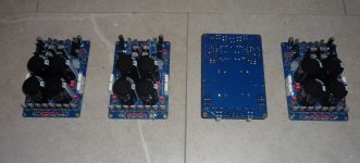
Completed my 4x SLB's ... and cleaned and lacquered the solder side.
Because I was ordering for 4 of them, I was able to get good matches for the same component on the '+' side and the '-' side of each SLB.
In addition, as I had 16x 15000uF caps in all, I was able to closely match the total capacitance on each DC rail.
I was able to get 28,440 / 28,420uF on one pair of SLBs (the same on the ‘+ve’ DC rail as the ‘-ve’) … and 28,400 / 28,390uF on the other pair.
Pity all the caps were 5% below spec, though ... rather than 5% above! 🙁
Now I have to create the flying leads for Q10 & Q12 - and then I can test them, to adjust output voltage to 20v, when drawing 3a. 🙂
Andy
Attachments
Thank you, zman & X. 🙂
However, the "proof of the pudding" will be when I connect up the load resistor I've knocked up (using a collection of 10w ceramic ww resistors & 12w Mills ww) ... and switch on each SLB! 😀
Testing this load resistor with my benchtop SMPS showed an output of 3.26a at 20v - so perfect for my 3a AN 4R boards. 🙂
Andy
Last edited:
Hey Andy, the actual "proof of this pudding", is when you connect it to your amplifier and listen to the difference in the sound- surprisingly, some people don't like the change.
Hey Andy, the actual "proof of this pudding", is when you connect it to your amplifier and listen to the difference in the sound- surprisingly, some people don't like the change.
Hah - you're jumping the gun, James. 🙂
Sure, listening to the AN amps is the ultimate test but I am waiting for my BangGood 'hot air soldering gun" to arrive, so I can finish the SMD components and then get on with the through-hole components on the AN PCBs.
Whilst I was waiting, I thought I would put my time to good use by building the SLBs - which are a necessary component of the final amplifiers. 😀
The difference in the sound will be how the AN 4Rs compare to the down-rated NAKSA 80s I am currently using on the:
* mids (3.2 ohms), and
* ribbons (2 ohms)
... of my 3-way active Maggies.
Andy
Perhaps you could try it out on Hugh's amp too - that'd be quite interesting …
I thought about trying it out on Anthony"s NVX200 module amp (with basic CRC supply)
I thought about trying it out on Anthony"s NVX200 module amp (with basic CRC supply)
Perhaps you could try it out on Hugh's amp too - that'd be quite interesting …
I thought about trying it out on Anthony"s NVX200 module amp (with basic CRC supply)
Not quite sure what you mean, James. 😕
The SLB is designed to power a Class A amp - which always operates at high current. Hugh's other amps - like my NAKSA 80s (and Anthony's NVX200) - are Class AB ... so a 'normal' CRC or CRCRC PS is the one to use.
Andy
No reason that the SLB won't work with a class AB amp, apart from the higher rail voltage limitations (particularly the active bridges) and the higher value output capacitors - there will be a bit of a difference between the high gain, high feedback type of "Capacitor Multiplier" (ie SLB) and a more passive types of filter (ie 'juma', FW, etc), but no reason they won't work okay
These power supply filters have been around for quite awhile, the active fet rectifiers are the fairly recent item in Diya but well established in industry.
These power supply filters have been around for quite awhile, the active fet rectifiers are the fairly recent item in Diya but well established in industry.
The main thing with standard Class AB amps is that they have very PSRR so don't need a PSU with only a 1mV ripple at 5A. They can get by with a basic CRC filter and because there is no output device to limit current, they probably have inherently a higher peak pulse current capability for bass dynamics. But it would be overkill to use the SLB if your amp has intrinsic -70dB PSRR. SE Class A amps have poor PSRR and that is why we need to work harder to give it clean ripple free power.
What kind of people don't like what kind of change? Can you be more specific?
surprisingly, some people don't like the change
What kind of people don't like what kind of change? Can you be more specific?
Many of us see an amplifier's power supply in terms of voltage, current, dB ripple, impedance, etc as these are the means by which we test and specify them - no problems at all
However, another term that's bandied around a lot is the "sound' of the power supply" applied to particular types of circuits and this introduces a lot of subjective references that aren't related to the engineering approach - here we're talking about power supply variations like C-L-C, Cap Mx, Regulated, Switch Mode, etc and even get into areas like the different sonic behavior of different types of the electro caps,and not only in power supplies (there's been a lot of 'agro' about this over the years and that's why it doesn't get mentioned much these days, I think)
Now to your specific question of what type of people might prefer the simple basic type of power supply (what we'd call lower quality I think) - well, here goes …
Some people (Diya or not)just don't hear any benefit so the more expensive supply is 'stupid' to them - that's a pretty common attitude.
Some people have amplifier/speakers that seem to sound better with the 'more basic' power supply and strangely enough, with those cheap block bridges for rectifiers and banks of cheap small electro caps. My brother likes the sound of a cheap old Marantz setup rather than any "audiophile" system and uses CDs, not a 'digital source' (yeah, well…!)
Some people just like to sit back and listen to a "softer" sound at home after spending a day with studio sound or teaching music, etc.
There are a lot of people that don't like the 'sound of digital music' despite the fact that almost all of it comes from a digital data-stream and like to think that simple amplifiers will produce a more 'natural' sound and valves, transformers and vinyl just "sounds better" - not exactly supporters of audio technical innovation, I must admit!
I once built an F5 amp for a mate, a 'u-beaut' version with regulated supplies and exotic components,and he had me replace the power supply with Phillips diodes and United Chem caps - it sounded "better' to him, go figure! We're all a bit different, some bigger "bit" than others, I guess.
So, as you can see (amidst some of my own prejudices too!), that my words are all about a subjective approach to listening/sound and, as Hugh has found, some extra 'colour' in the amp can produce a 'better sound' for some people - this also applies to the power supplies as they are in the loop of amplifier and speakers.
Sorry I can't give you a more specific answer but people from all sorts of music seem to be quite a 'fickle' group indeed when it comes to equipment, not just Diya.
Yes, I agree about the class AB amps being less demanding of power supply performance but you can 'possibly' obtain "better sound' from an AB amp with a better power supply like the SLB (that's what I meant to say...)
Hi X, Hugh,
Fired up my first SLB - with my 6.2 ohm load res first between PVout & earth - and then between earth & NVout.
No 'magic smoke' - all that happened was the load res got very hot ... but Q10 & Q12 were both barely warm (on their heatsink). 🙂
Only trouble is ... with RV1 & RV2 turned to give the lowest output voltage - I am reading:
* + 21.6v for PVout, and
* - 21.7v for NVout.
(So I probably should've used 16v toroids - not 18v. 🙁 )
Can I reduce PVout & NVout by replacing RV1 & 2 with a higher value Bourne pot - like 1K?
Given I'm using my AN4R on 2 ohm ribbons ... I don't want to stress it even more by increasing its DC rails above the nominated +/- 20v. 🙁
Sure, I know this will increase the wattage through Q10 & Q12 - but as they are barely warm at present ... I'm thinking this shouldn't be a problem?
Thanks,
Andy
Hi Jameshillj,
I appreciate your extended answer. I agree that many people like simple PSU’s for some reason. I am not sure why boutique bulk caps would sound better though in a CRC. I do think that active bridges like LT4320 is quieter and helps a Class AB amp or a low current preamp even.
I appreciate your extended answer. I agree that many people like simple PSU’s for some reason. I am not sure why boutique bulk caps would sound better though in a CRC. I do think that active bridges like LT4320 is quieter and helps a Class AB amp or a low current preamp even.
Hi AndyR,
That’s a good result you have there. It’s always better to have some reserve for headroom. You could just add three 1A10 diodes or 3x MUR880 TO220 diodes in series between the SLB and your amp to drop it by 1.8v. That’s about the easiest fix. You can also remove some secondary windings from your trafo. If it were me, I would leave it there and be happy that I got a few extra volts. Changing the pot is expensive vs changing the resistor in series with the pot to a bigger one.
That’s a good result you have there. It’s always better to have some reserve for headroom. You could just add three 1A10 diodes or 3x MUR880 TO220 diodes in series between the SLB and your amp to drop it by 1.8v. That’s about the easiest fix. You can also remove some secondary windings from your trafo. If it were me, I would leave it there and be happy that I got a few extra volts. Changing the pot is expensive vs changing the resistor in series with the pot to a bigger one.
Hi AndyR,
That’s a good result you have there. It’s always better to have some reserve for headroom. You could just add three 1A10 diodes or 3x MUR880 TO220 diodes in series between the SLB and your amp to drop it by 1.8v. That’s about the easiest fix. You can also remove some secondary windings from your trafo. If it were me, I would leave it there and be happy that I got a few extra volts. Changing the pot is expensive vs. changing the resistor in series with the pot to a bigger one.
Changing the resistors (R11 & R12) is a good suggestion, X. 🙂 I had some 121 ohm reses lying around - so I changed R12 on one SLB.
It was not an easy exercise - due to the fact that this res is right next to the Bourne pot - first to get the original res out ... then get some nice clean holes ... and then put the new res in. 🙁 So I did it for one, to see if it would reduce the -ve DC rail.
It didn't make much difference! 😡 So I suspect your values of 75R and 200R need to be quite a bit higher (to allow for a bit of adjustment) when the DC output of the SLB is only +/- 20v.
BTW, my situation is not helped by the fact that my mains voltage is 247v - instead of the 240v the traffos were specced for! 😡 My traffo secondaries were reading around 19.75v, instead of 18v - which would explain the DC rails I was getting!
Anyway, I left all the other 75 ohm reses in place and will live with the DC rails I can achieve, when I match +ve and -ve on each SLB.
However, I might add 3x diodes in series with each DC rail (to drop 1.8v), after I see how the SLB performs, when driving an AN 4R PCB with a 2ohm load.
Re. diodes - why can't I use:
* the 5a SB5100T (DiodesZetex)
* or the 6a P600M-E3/54 (Vishay)?
Andy
- Home
- Group Buys
- The SLB (Smooth Like Butter) Active Rect/CRC/Cap Mx Class A Power Supply GB