
Why?
Hi JP,
It seems like common advice lately in amp/preamp restorations/recaps that replacing the lower value electrolytic caps with film types is the way to go, and I've actually done so in some preamps and amps I have recapped.
Also the benefits of films; lower esr, higher ripple current, don't dry out, and longer life would seem to benefit here.
But again, I'm not sure if any of the 4 boards have to have electrolytic because of design, polarity or something I'm not aware of.
Seeing as there are about 23 caps with 10uf lower value out of the 50 some odd caps total, I figured as long as it fits go with the film type.
Longer life is the only benefit you'd likely see here, and as there would still be several electrolytics in there it wouldn't seem to matter. For the dozens of units I've been in, it tends to be the larger values that get tired first.
I see, well I guess it won't hurt then.
On another note, I purchased your FA6042 IC probably about a year and a half ago, at the time I thought I had secured a MK3 but the deal fell through, the IC is still sealed in it's package. I was finally able to purchase a MK3 and will be dropping in your IC soon. Thanks for including an IC socket, I just noticed it was included the other day, I had kept telling myself to order a socket but now I don't have to, it will make dropping in the newer and improved IC you design in the future easier 😀
On another note, I purchased your FA6042 IC probably about a year and a half ago, at the time I thought I had secured a MK3 but the deal fell through, the IC is still sealed in it's package. I was finally able to purchase a MK3 and will be dropping in your IC soon. Thanks for including an IC socket, I just noticed it was included the other day, I had kept telling myself to order a socket but now I don't have to, it will make dropping in the newer and improved IC you design in the future easier 😀
I was going to ask about that, I remember it said that somewhere on your site, when I went back recently I didn't see it there.
So jump R212 as well, what's the significance of jumping this two locations?
So jump R212 as well, what's the significance of jumping this two locations?
For the bearing, after cleaning with 99.9% IPA, can I use Anderol 465? I still have a full bottle that I used for my 1200. Would I add a drop on the thrust pad at all, or just lube up the bore and bearing shaft.
Thank you.
Thank you.
Anderol 465 or similar ISO-68 is the right stuff. I give the bore, shaft, and thrust a nice coat before assembly, and then a drop or two at the top of the shaft after assembly for good measure.
Gents, can I please ask for your guidance, I need some help from your expertise and understanding of the topic.
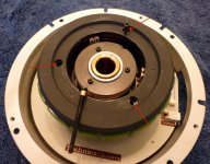
I am in the process of designing the plinth for my SP-10 Mk3. Will separate it from the chassis and mount it directly into a Panzerholz plinth (brake and strobe will be removed).
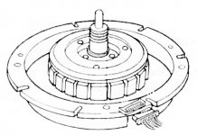
As the motor pan isn't too high, quite a substantial part of the motor unit will be visible - including almost all of the magnets. @JP, I am borrowing two of your pictures here from the beginning of the thread if that's ok, those clearly show the sections that will be exposed. Also the exploded view from the Manual shows the section and the dimensions quite well (also attached).
My question is: as these are magnets, and coils underneath, all typically covered up in the chassis but freely exposed here - do I need to take precautions of keeping magnetic and electrical interferences kind of radiating away from that area, eventually finding their way into the cartridge or other equipment etc.? I will likely not have another layer/plate of the plinth covering it up, so would it make sense to put kind of a brace/bracket, e.g. from mu-metal or so, around it?
Thank you,
Robert
I am in the process of designing the plinth for my SP-10 Mk3. Will separate it from the chassis and mount it directly into a Panzerholz plinth (brake and strobe will be removed).
As the motor pan isn't too high, quite a substantial part of the motor unit will be visible - including almost all of the magnets. @JP, I am borrowing two of your pictures here from the beginning of the thread if that's ok, those clearly show the sections that will be exposed. Also the exploded view from the Manual shows the section and the dimensions quite well (also attached).
My question is: as these are magnets, and coils underneath, all typically covered up in the chassis but freely exposed here - do I need to take precautions of keeping magnetic and electrical interferences kind of radiating away from that area, eventually finding their way into the cartridge or other equipment etc.? I will likely not have another layer/plate of the plinth covering it up, so would it make sense to put kind of a brace/bracket, e.g. from mu-metal or so, around it?
Thank you,
Robert
Attachments

Hi JP,I don't think you'll have a problem.
Are you still repairing the Technics EPA 100 tonearms? I sent an e-mail through your site about a month ago but have not received a reply. I apologize if you are no longer doing this and have made it known before. Let me know.
Thanks.
Ok no problem, thanks for the reply and update.Am when I'm able but backed up with a contract gig ATM. Thing should ease up after November. Will look for your message.
My biggest beef with all Panasonic tables, and I used to be a tech for them in Chicago, is that they do not have overlapping field coils. This results in slightly higher flutter than other tables. The only DD I know of with overlapping field coils was made by Sony, a friend had one that I got to measure, and flutter was a bit lower. As a result of being able to measure Panasonic tables, I always stuck to belt drive, usually VPI. Not that your TT is not well made. It's actually very well made. But that one thing always bugged me...
I recently came across an SP-10Mk3 without the PSU. I'd greatly appreciate any thoughts on the likelihood of finding a factory PSU? Would it be a fool's errand to attempt to build one?
They pop up on Yahoo every now and again. I think I’ve seen 5 in the last 6-7 years.
It’s the same chipset as the SL-1300/1400/1500MK2, SP-15, and SP-10MK2A sans pitch control. You could use one of those as a base and hang a beefier output stage for the drive phases.
I’m aware of someone who did it with an SL-1300/1400/1500MK2. Worked okay but needed a hand start as they didn’t implement a larger output stage on it. The only platform that has the same ‘tuneability’ is the SP-10MK2A, but it’s more involved to take advantage of it as you’d need to add current sensing to the new output stage, etc. Not that difficult but a bit of a science project. Then again the MK2A may have enough juice on its own.
- Home
- Source & Line
- Analogue Source
- The Incredible Technics SP-10 MK3 Thread