Hi John, are you writing the PIC code ? A great job here, as you know I use a DDS on the SL-1200 speed control.
Regards
Dave
Regards
Dave
I didn't know that. DDS seemed the most logical choice to me. I briefly looked at using the clock off the DN860, but it just didn't make sense to go that route.
I wrote it in C using MPLAB X. I skipped the 'blink LED' tutorial, but managed to get it cobbled together in not quite one week.
I wrote it in C using MPLAB X. I skipped the 'blink LED' tutorial, but managed to get it cobbled together in not quite one week.
Well done, the DDS is one of the least known devices and one of the cleverest. The one we use produces a better clock if you take the sinewave and threshold it, rather than the square wave. Of course it might be the layout which is beyond belief critical.
If I hadn't of been so ill, we might have discussed this; but the drugs had kicked in.......................
Dave
If I hadn't of been so ill, we might have discussed this; but the drugs had kicked in.......................
Dave

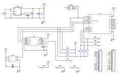
Here's a bit of an update. The schematic is what I've had running on the breadboard for the last several weeks. I've gone back to using the square wave output of the DDS as the DN860 chip has no issue with it, and it reduces complexity and layout sensitivity. On the breadboard setup the output of the DN860 is good to +/- 0.00001Hz. I've no idea how my table measures; I'll check when I next have it open.
This is the first board I've ever done, so I'm going to sit on it for a few days before having a couple prototypes made up.
This is the first board I've ever done, so I'm going to sit on it for a few days before having a couple prototypes made up.
Attachments
So? It's his prototype. Probably need to determine if it actually works before releasing it to the world...
Looking good. I expect the DDS is decoupled well. Not sure the pull ups are required, but hey, it's a breakthrough concept !
Not local, but the board is so small I'm not sure I need more, and upon initialization I'm powering down the DAC. Works good on the breadboard anyway.
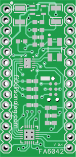
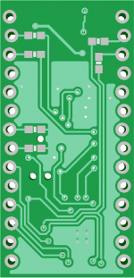
I did remove the pull ups on the SPI lines as they're not needed. This allowed a little bit of breathing room in the layout, which allowed a continuous ground pour. I also switched the current limiting resistors out for diodes.
I'll upload new images in the next few days. I hope to get it out for prototype boards early next week.
I'll update the schematic later, though here are the changes:
1) Added local decoupling to the oscillator, DDS, and PIC.
2) PIC and DDS are running off 5V, oscillator off the 3.3V regulator. It's quite difficult to find 5V TCXO's, and I couldn't run the PIC off 3.3V as high wasn't high enough for the LED display to work right.
3) I'm using a programmable TCXO at 8.386560 so that /32 is the nominal clock we need: 262.080KHz. It doesn't seem to make much of a difference for this application, but if the output frequency of the DDS isn't an integer of MCLK, there's quite a bit of jitter in the output due to the averaging the DDS does.
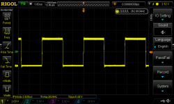
4) Added 100pF across the output to take care of some rather severe overshoot.
5) Took care of some pinout issues.
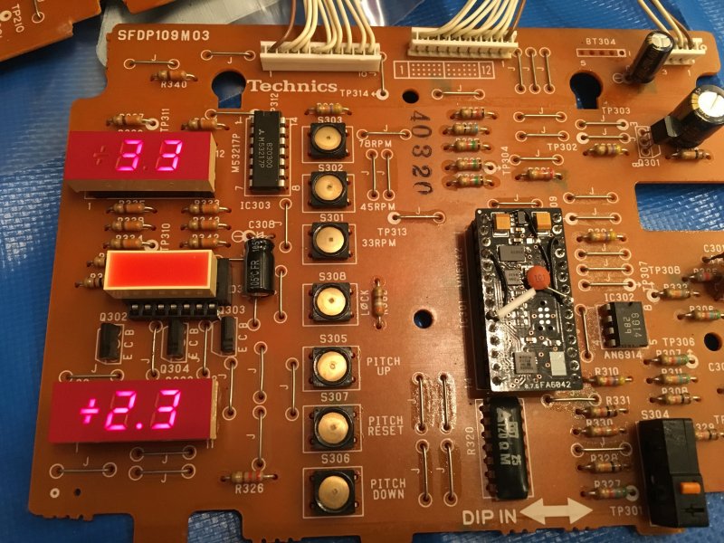
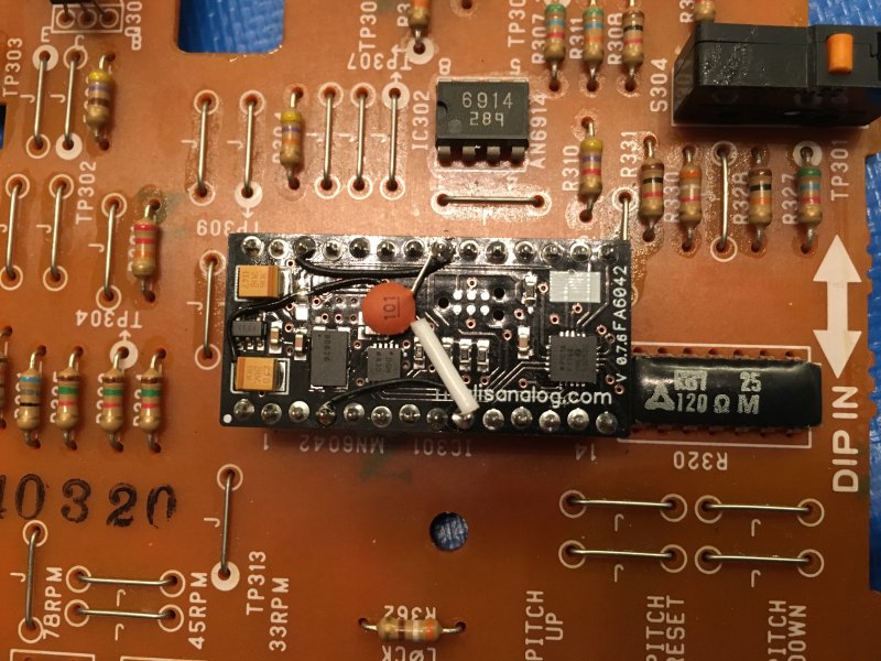

I measured three MN6042 parts before putting this in. Two measured +1/-7 Hz, and one measured +0/-7 Hz. The replacement board measures +0.1/-0.2Hz. That'll do.
I didn't measure the DN860 output as there isn't one if the table isn't running, and I didn't have the motor hooked up. On the breadboard with a DN860 I'm getting 50.55566Hz +/-0.00002Hz at 0 pitch. When I adjust pitch which adds a bit of jitter from the DDS I get about the same though it fluctuates at a higher frequency, and more to the extremes.
I may revisit and use the sine output with a comparator to mitigate the jitter, but I don't think it'd make any practical differences.
1) Added local decoupling to the oscillator, DDS, and PIC.
2) PIC and DDS are running off 5V, oscillator off the 3.3V regulator. It's quite difficult to find 5V TCXO's, and I couldn't run the PIC off 3.3V as high wasn't high enough for the LED display to work right.
3) I'm using a programmable TCXO at 8.386560 so that /32 is the nominal clock we need: 262.080KHz. It doesn't seem to make much of a difference for this application, but if the output frequency of the DDS isn't an integer of MCLK, there's quite a bit of jitter in the output due to the averaging the DDS does.
4) Added 100pF across the output to take care of some rather severe overshoot.
5) Took care of some pinout issues.
I measured three MN6042 parts before putting this in. Two measured +1/-7 Hz, and one measured +0/-7 Hz. The replacement board measures +0.1/-0.2Hz. That'll do.
I didn't measure the DN860 output as there isn't one if the table isn't running, and I didn't have the motor hooked up. On the breadboard with a DN860 I'm getting 50.55566Hz +/-0.00002Hz at 0 pitch. When I adjust pitch which adds a bit of jitter from the DDS I get about the same though it fluctuates at a higher frequency, and more to the extremes.
I may revisit and use the sine output with a comparator to mitigate the jitter, but I don't think it'd make any practical differences.
Attachments


🙂 An update on an old thread.
John's chip has revived several SP-10 MK3's here in the UK. It fixes dead turntables and makes them better than new.
I have also revived over a handful of the Technics SP-15 with the same chip too.
John's chip has revived several SP-10 MK3's here in the UK. It fixes dead turntables and makes them better than new.
I have also revived over a handful of the Technics SP-15 with the same chip too.
Last edited:
For the benefit of others I just repaired yet another MK3, this time the secondary 12V regulator Q280 that feeds the strobe and brake (?) was O/C with burn marks. The symptom was no strobe.
As R282 is only dropping 1.66V leaving Q280 to do most of the work and exceeding 100 degrees C, can anyone suggest why R282 would not be better off at say 27R ?
Late production they moved Q280 to the heatsink.
That would be sensible ! I'll go to a bigger and 3W dropper.
Anyone know where I can get a set of platter removal tools?
I just bought a SL1000 MK3 and the seller does not have the platter removal tools to remove the platter and safely ship the turntable.
I just bought a SL1000 MK3 and the seller does not have the platter removal tools to remove the platter and safely ship the turntable.
You’re going to hunt me down on every forum I’m a member, eh? 🙂
32429 L.652/40 p-M6x20 Elesa L.652 Handle Threaded M6 X 20 – Steel City Supply
Tell the seller to only thread them in 5-6 turns. The platter holes are through, and if he goes too far he’ll hit the chassis underneath.
32429 L.652/40 p-M6x20 Elesa L.652 Handle Threaded M6 X 20 – Steel City Supply
Tell the seller to only thread them in 5-6 turns. The platter holes are through, and if he goes too far he’ll hit the chassis underneath.
You’re going to hunt me down on every forum I’m a member, eh? 🙂
32429 L.652/40 p-M6x20 Elesa L.652 Handle Threaded M6 X 20 – Steel City Supply
Tell the seller to only thread them in 5-6 turns. The platter holes are through, and if he goes too far he’ll hit the chassis underneath.
Thank you very much for the info!
And to your comment, my post was not directed at you in particular, in fact, did not even notice... it was a general call for help 🙂
- Home
- Source & Line
- Analogue Source
- The Incredible Technics SP-10 MK3 Thread