Calvin, I'm still interested in your formula. Please contact me via email, PM on the board is disabled.
Coating formula
Hi Calvin
I'm building my second pair of ESL's. The first one I used a coating
supplied by Rob McKinlay of ERAudio with good results, except
that it's not immune to humidity. Besides it's kind of expensive
and with shipping from Australia becomes a little more, of course.
My second pair of ESL's are in the works, the membrane is not
stretched yet and the compound is almost finished and is not enough for these six panels.
So, I would be very much interested in knowing your formula
even if this represents some expense for me.
My e-mail is
Joaomateus11@earthlink.net
I'd appreciate.
I'm getting the "ER" coating. Its been reformulated. I bet "EC" is just as good
but there are some other items ER has that I want. The price is not like buying
an expensive stepup trafos.
The secret coating posts in this thread remind me when a lady in a posh New York
restaurant asked the chef for the recipe on the desert she loved. He gave it to her in writing & there was a big $$ charge on the bottom of her dinner tab. She was so
outraged it made the newspapers. Better than a lemon meringue pie in the face
I always say.
Lucius
hmmmphh
Hi,
well guys, I´d like to comment on some things I find quite strange.
The way somebody handles the informations he/she is willing to share is solely up to him/here. To give infos openly always carrys the risk that someone else simply copies and sells the stuff. I dislike such a behaviour and so I decide from case to case who I like to give an info.
What makes me really angry is, that guys asking for infos have theire PMs inactive or even better..mails can´t be delivered without registering -ey Joao!! It usually takes me some time to write good and understandably infos and I have no understanding for guys asking for infos but not providing for easy deliverance. You want infos? Than make it possible!
jauu
Calvin
What makes me really angry is, that guys asking for infos have theire PMs inactive or even better..mails can´t be delivered without registering -ey Joao!
Mea Culpa.. I didn't realise my E-Mail link for this forum was expired. So if anyone did
try to get a hold of me it works now. Calvin, even if you did not E-mail me, thanks
for bringing this up.
Lucius
Information
Hello Calvin
Thanks very much for the info.
I received this morning.
Thanks again.
Joao
Hello Calvin
Thanks very much for the info.
I received this morning.
Thanks again.
Joao
Re: hmmmphh
Hi Calvin,
I'm still interested in your coating formula, if you would care to share it. I haven't built any ESL panels yet, as I'm still in the 'imformation collection' stage, reading as much as I can find and trying to learn the benefits and issues of the various approaches. I would be interested in your 'formula' to continue my education and hope of building a 'good' ESL on my first attempt.
I don't have any commercial interest in selling your coating or speakers that would use it.
I can be reached at tommak@mindspring.com
Thanks for your contributions to the diyAudio forum!
Regards,
Tom
Calvin said:Hi,
well guys, I´d like to comment on some things I find quite strange.
The way somebody handles the informations he/she is willing to share is solely up to him/here. To give infos openly always carrys the risk that someone else simply copies and sells the stuff. I dislike such a behaviour and so I decide from case to case who I like to give an info.
What makes me really angry is, that guys asking for infos have theire PMs inactive or even better..mails can´t be delivered without registering -ey Joao!! It usually takes me some time to write good and understandably infos and I have no understanding for guys asking for infos but not providing for easy deliverance. You want infos? Than make it possible!
jauu
Calvin
Hi Calvin,
I'm still interested in your coating formula, if you would care to share it. I haven't built any ESL panels yet, as I'm still in the 'imformation collection' stage, reading as much as I can find and trying to learn the benefits and issues of the various approaches. I would be interested in your 'formula' to continue my education and hope of building a 'good' ESL on my first attempt.
I don't have any commercial interest in selling your coating or speakers that would use it.
I can be reached at tommak@mindspring.com
Thanks for your contributions to the diyAudio forum!
Regards,
Tom
Please send info on coating to atom1@sympatico.ca.Here is the link to my ESL project http://www.diyaudio.com/forums/showthread.php?s=&threadid=71171&perpage=10&highlight=&pagenumber=2
Thanks
Andrew
Thanks
Andrew
Member
Joined 2003
Hi Calvin,
I do not know why PM did not work because it is supposed to be enabled. Anyhow, EM address is pnwright3@yahoo.com
I did not intend to frustrate you...sorry.
Best regards,
Paul
I do not know why PM did not work because it is supposed to be enabled. Anyhow, EM address is pnwright3@yahoo.com
I did not intend to frustrate you...sorry.
Best regards,
Paul
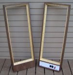
Here's a photo of the frames with walnut veneer applied. They have two coats of tung oil and still need a topcoat of polyurethane. After that, a buff with fine steel wool and the finishing will be done. It has been humid here so I'll let them sit for another day before topcoating.
The frame on the left is a front view. I'm going to use a neon lamp on the output of each high voltage power supply. I was going to mount the neon lampholders on the front and centered in the lower part. I'm not sure if I want to drill through the front after seeing the frame with veneer on. The lampholders might end up on the back cover.
The frame on the right is a back view and shows the white back cover with IEC and speaker connectors. The IEC connector on the left is the power in and has an integral 5mm x 20mm fuseholder. The other IEC connector feeds power to the second speaker through a male-female IEC cord.
Attachments
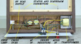
Here's a look at the electricals for one speaker. The rails that hold the back cover in place aren't shown in the picture. The high voltage wire is 18 GA sheathed in 7/32" diameter clear aquarium tubing to give a bit of insurance against arcing.
Follow the link to the .pdf file of the power supply. I measured 360 volts with a VTVM at the output of the step-up transformers, less than I expected. No problem, though. There's still enough voltage at the output of the voltage multiplier at the X10 setting to arc between two test plates of perforated steel 0.080" apart.
Follow the link to the .pdf file of the power supply. I measured 360 volts with a VTVM at the output of the step-up transformers, less than I expected. No problem, though. There's still enough voltage at the output of the voltage multiplier at the X10 setting to arc between two test plates of perforated steel 0.080" apart.
Attachments
Hi Bill H,
nice work !
I looked at the power supply. You shouldn't connect the output of T2 directly to the ground of the cascade, but implement a 20Mohm resistor to avoid hum by capacitive coupling.
What size is your stepup ? it looks like EI 84. I guess with this small sized stepup you wont drive your ESL fullrange ?
Capaciti
Thanks, Capaciti. You can't tell from the picture, but the 20 meg resistor is on the HV bias supply board farthest away from you in the photo. It's made up of ten 2 Megohm resistors. It's a modification I made to Roger Sander's design to use readily available components.
The transformer core measures 73mm wide x 64mm high. The manufacturer recommends a low frequency cutoff of 225 Hz. It won't be used as a full range, I've got a TL woofer to provide the low end.
The transformer core measures 73mm wide x 64mm high. The manufacturer recommends a low frequency cutoff of 225 Hz. It won't be used as a full range, I've got a TL woofer to provide the low end.
The picture below shows a crossover frequency response chart and the simplified ESL circuit. All resistors shown are made up of multiple 1 watt units to withstand the voltage and current demands of the ESL panels.
The frequency response test setup was frequency generator --> audio transformer --> crossover --> VTVM with capacitors of close to the calculated ESL capacitance installed where the ESL sections would be. Although my method was crude, the graph shows the crossover overlap and cutoffs that gave the smoothest summed response without excessive current draw from the amplifier. Note the linear frequency scale on the chart. It's done with MS Excel and I don't know how to get a Log scale on the x axis.
The frequency response test setup was frequency generator --> audio transformer --> crossover --> VTVM with capacitors of close to the calculated ESL capacitance installed where the ESL sections would be. Although my method was crude, the graph shows the crossover overlap and cutoffs that gave the smoothest summed response without excessive current draw from the amplifier. Note the linear frequency scale on the chart. It's done with MS Excel and I don't know how to get a Log scale on the x axis.
Attachments
Hi BillH,
i didn't mean the 20 meg resistor for the output. I meant an additional resistor between ground of the HV-Supply and the center tap of the stepup.
I looked onto your schematic. What is the purpose of R1,C1,R2,C2 ?
Capaciti
i didn't mean the 20 meg resistor for the output. I meant an additional resistor between ground of the HV-Supply and the center tap of the stepup.
I looked onto your schematic. What is the purpose of R1,C1,R2,C2 ?
Capaciti
Capaciti writes: You shouldn't connect the output of T2 directly to the ground of the cascade, but implement a 20Mohm resistor to avoid hum by capacitive coupling.
I haven't seen a second 20 Meg resistor used in that position before. I could be wrong, but the ground of the cascade seems to be at 0 volts DC in relation to the output. I'll measure the output after the first rectifier to see if there's any AC signal there when I get home later.
I looked onto your schematic. What is the purpose of R1,C1,R2,C2 ?
They are RC high pass filters for the high frequency sections of the ESL, based on this.
Hi,
Sorry for a bit off-topic reply , but i would like to ask what is the difference between using copper versus aluminium foil for contacts to diapraghm. By the way , i have found a simple tool to cut aluminium foil - razor blade.
Regards,
Lukas.
Sorry for a bit off-topic reply , but i would like to ask what is the difference between using copper versus aluminium foil for contacts to diapraghm. By the way , i have found a simple tool to cut aluminium foil - razor blade.
Regards,
Lukas.
Hi Bazukaz,
NEVER use aluminium. There will be an isolating oxide layer by time and contact will be compromised !
capaciti
NEVER use aluminium. There will be an isolating oxide layer by time and contact will be compromised !
capaciti
Hi Bill,
is the tweeter-panel with the same d/s as the bass-mid-range panels?
Than I wouldn´t use any high-pass-filtering, because You need every peace of area for a good efficiency of the speaker. In case the tweeter-panel is designed with smaller d/s You my use an RC-filter, but I´d suggest smaller values for C as well as R.
C can be chosen smaller, but not less than 10 times the speaker capacity. A quick simu based on Your speakers capacity value showed that 10nF + 30kOhms give -3dB freq of ~500Hz, 20kohms ~730Hz and 10kOhms ~1.4kHz.
jauu
Calvin
Hi BillH,
Calvin is right. If you do not have different D/S spacing you should not use the filter. Any filter compromises the phase response of the system.
Especially onESL you can "hear" any filter involved.
Calvin is right. If you do not have different D/S spacing you should not use the filter. Any filter compromises the phase response of the system.
Especially onESL you can "hear" any filter involved.
- Status
- Not open for further replies.
- Home
- Loudspeakers
- Planars & Exotics
- The ESL Build Thread