I_Forgot writes: If a single tube won't stretch to fit, you can use two tubes, one for the upper and one for the lower half of the driver.
--
| |
| | top half
--
--
| |
| | bottom half
--
How would you would get the diaphragm coated and attached to the stator while it's in the stretching jig? Wouldn't the center, where the two tubes pass each other be in the way?
The tube(s) are under the diaphragm, around the edge of a "table" made of a piece of plywood.
see photos in this thread:
http://www.diyaudio.com/forums/showthread.php?s=&threadid=60391&perpage=10&highlight=&pagenumber=3
I_F
see photos in this thread:
http://www.diyaudio.com/forums/showthread.php?s=&threadid=60391&perpage=10&highlight=&pagenumber=3
I_F
Hi Bill H,
the tension applied by 4 weights of about 100-500grams only is much less than mylar or hostaphan can sustain. So this method do not fully utilize the mechanical capabilities.
Thats why the author mentions that heat shrinking will increase fundamental resonance.
You are correct that the shrinkage rate is different depending on axis orientation, but even 2% is more than enough headroom to stretch a membrane which is glued to the frame having visible wrinkles.
Capaciti
I_Forgot writes: The tube(s) are under the diaphragm, around the edge of a "table" made of a piece of plywood.
Ah, now I understand. My situation is a little different. I've been planning to have a stretcher with an open middle section and a 1-1/2" thick removeable table slightly larger than the ESL stator. One side of the table, made from two layers of 3/4" chipboard will be flat and the other side will have spacers to pass my acrylic supports when the stator is set on it.
The order of assembly would be:
1) Mount the film to the stretcher and give it enough tension to get the wrinkles out.
2) Insert table with flat side up into stretcher and apply graphite. 3) Retension to Fo.
4) Remove stretcher with the film still on it, flip table, and set stator on table.
5) Apply glue to stator and drop the stretcher and film on to the stator.
The 'Charge Ring' made of copper foil will be on the other stator, in contact with the graphite.
Capaciti writes: You are correct that the shrinkage rate is different depending on axis orientation, but even 2% is more than enough headroom to stretch a membrane which is glued to the frame having visible wrinkles.
It would be so much easier to just glue the diaphragm and heat it as you recommend. My only concern would be trying to get a desired Fo with a material that has a finite heat stretching limit. These panels are meant to have a ~100 Hz Fo on the 4-1/2" x 36" sections when assembled, but I need to stretch the diaphragm as a single 12-3/4" x 36" unit. I'm doing the math now to see what that Fo would need to be.
Tension tool
Here's a tension tool that I've been using in stretching the mylar
with great success. It works around the membrane stretching
it as I go around, fixing the stuff with a strong tape. After done
all I have to do is to glue the frame to it, it remains stretched
forever....
This is a smart tool bought from Eraudio.com.au sometime ago.
Attachments
jmateus: Could you attach a full-sized image of the tool you're describing? I'm having a hard time making out the details in the thumbnail-sized image.
Thanks.
Thanks.
Capaciti said:Hi I forgot,
Thats true, but a mechanically stretched membrane will increase its compliance and reduce resonance over the time.
people wonder why a new mechanically streched membrane ist stable first and collapses months later.
My experience is that over years the stretched membrane "creeps". It stops exactly at the tension of a heat shrinked . When it stops depends on listening level and membrane excursion.
Capaciti
Months? I built my first ESL drivers about 15 years ago. They were mechanically stretched. Those drivers still play as new, even with >3 kV bias. I used 6 um thick "lumilar" polyester film made by Toray.
I have tried heat shrinking the film and it works but the tension can never get near what I can do with the pneumatic stretcher. I have used the pneumatic stretcher to replace some diaphragms in my Quad ESL-63s and they are perfectly stable even with the 5.25kV bias voltage and the thin insulators.
Quad used a mechanical stretcher for the original diaphragms. I saw a picture of it in Speaker Builder magazine once (or was it Audio Amateur?). It was some complex mechanism with dozens of little fingers that pulled on the film. When a Quad diaphragm fails, it usually splits near the edge of the driver, or the glue lets go. I have never heard of one "relaxing".
I_F
BillH said:
The order of assembly would be:
1) Mount the film to the stretcher and give it enough tension to get the wrinkles out.
2) Insert table with flat side up into stretcher and apply graphite.
3) Retension to Fo.
How do you determine F0?
4) Remove stretcher with the film still on it, flip table, and set stator on table.
5) Apply glue to stator and drop the stretcher and film on to the stator.
I think you may find that having the table separate from the frame and having to move parts in and out over the tensioned film will make it hard to assemble the speaker without poking holes in the film, especially considering how large the driver is and therefore how heavy the frame and table must be.
These panels are meant to have a ~100 Hz Fo on the 4-1/2" x 36" sections when assembled, but I need to stretch the diaphragm as a single 12-3/4" x 36" unit. I'm doing the math now to see what that Fo would need to be. [/B]
How did you decide that the resonance should be 100 Hz? How do you translate the tensioning process into a predictable F0? How do you square the tension required for a specific resonance with that required to remain stable at any particular bias voltage?
As far as I know, any rectangular shaped driver will have at least two resonances- one corresponding to the short dimension and another corresponding to the long dimension. There will also be resonances at harmonics of the two fundamental resonances.
Finally, I suggest that you forget the graphite and use Licron. The only complaints I have heard about it is that it doen't give an optically clear result, and it is a little expensive. You won't get that with graphite either, but Licron application is very easy, and doesn't risk tearing the diaphragm. The resistivity is MUCH higher than you can achieve with graphite, which keeps distortion to a minimum.
I started using Licron about 6 months ago, and the drivers are still playing as new. Others have reported a least a couple years (and counting) on this forum.
I_F
Stretcher
Hi Few
Unfortunately I wasn't able to get a better image of the stretcher
no matter what I did, I have a hell of a time trying to get a good
picture every time due to the constrains of size.
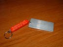
Anyway the strecher is a very pratical device that does the job,
the red part is a dinamometer calibrated in kilograms, the white
part is an aluminun plate where you tape the membrane temporarily until you stretch it to your wish. Once you attain
the desired tension you untape the membrane and tape it again against the surface you have it down. And you go around the
membrane doing the same and paying attention to the desired tension
which should be the same around the perimeter of the mylar.
At the end you'll have a tensioned membrane to your requirement
taped all around. Then you need to glue the the structure of the stator to the membrane, that's all.
I hope this long explanation described the stretcher to your contempt.
Hi Few
Unfortunately I wasn't able to get a better image of the stretcher
no matter what I did, I have a hell of a time trying to get a good
picture every time due to the constrains of size.
Anyway the strecher is a very pratical device that does the job,
the red part is a dinamometer calibrated in kilograms, the white
part is an aluminun plate where you tape the membrane temporarily until you stretch it to your wish. Once you attain
the desired tension you untape the membrane and tape it again against the surface you have it down. And you go around the
membrane doing the same and paying attention to the desired tension
which should be the same around the perimeter of the mylar.
At the end you'll have a tensioned membrane to your requirement
taped all around. Then you need to glue the the structure of the stator to the membrane, that's all.
I hope this long explanation described the stretcher to your contempt.
Your device, as best I can tell from the small picture, looks a lot like a portable fish weight scale. It is a simple spring-loaded thing with scale markings. It measures tension.
Jmateus: Thanks for the description. Even without the larger image I now get the picture (sorry...).
I was going to try setting up a microphone-->pc sound card-->fft software and tap the tensioned film to see if I could read the resulting frequency with the fft software.How do you determine F0?
Roger Sanders' book has a table that shows lowest frequency on an ESL panel vs. diaphragm to stator spacing and my ~0.055" spacing gives about 200 Hz. I figured Fo one octave lower should be about right. I may have to increase the 200 Hz Fo a bit. The transformers I'm using have a recommended 225Hz lower limit.How did you decide that the resonance should be 100 Hz? How do you translate the tensioning process into a predictable F0? How do you square the tension required for a specific resonance with that required to remain stable at any particular bias voltage?
I have to agree. I tried graphite as the low cost alternative for coating, but had questionable results on a few test pieces of film. I had a very hard time getting an even, high resistance coating. It was easy to get it too little or too much graphite on. I'll have to order the Licron. Mouser.com has it in stock. I still need to order four SMD capacitors for one of the crossovers anyway that I've forgotten to order twice. Gotta give it a day or so to see if I need anything else.Finally, I suggest that you forget the graphite and use Licron.
Now I have a question for the group. I've built the bias supplies with 100 meg series resistance because of a formula in Sander's book that predicts resistance needed to provide constant charge according to lowest frequency desired. I don't have the book handy right now, but if you need the formula let me know. Most of the bias supplies I've seen on the net are using 10-20 meg resistance. Do you think it makes any difference?
The stretcher jig version 1.1 is done and looking good if I must say. Check back later for a picture.
I wrote: These panels are meant to have a ~100 Hz Fo on the 4-1/2" x 36" sections when assembled, but I need to stretch the diaphragm as a single 12-3/4" x 36" unit. I'm doing the math now to see what that Fo would need to be.
If my math is right, I would need to tension the panel as a whole to ~22Hz to get the 4-1/2" wide sections to 100 Hz Fo. I don't know if I would be able to accurately measure 22Hz. Is this desire to meet a certain Fo a waste of time?
Here's another question for the group, but first a recap of the stator dimensions. Each ESL panel has two pairs of stators arranged as four 36" long strips. The two outside strips are 4-1/2" wide and the inner two strips are 1-1/2" wide. Do you think I'll need any extra horizontal support anywhere along the 36" dimension? I had thought of splitting the length into two or three shorter sections.

BillH said:If my math is right, I would need to tension the panel as a whole to ~22Hz to get the 4-1/2" wide sections to 100 Hz Fo. I don't know if I would be able to accurately measure 22Hz. Is this desire to meet a certain Fo a waste of time?
I have a couple comments here. First, I have never been able to discern any audible difference in panels other than the low frequency output level based on anything other than the combined area of the drivers. Thin insulators limit maximum excursion and so limit the maximum volume at low frequencies. But you can't separate that limit from the front to back phase cancellation at low frequencies. So is what I hear due to F0 or due to the phase cancellation? Both, but I suspect the overall size is far more important than F0 of any driver or section of any driver.
I think your planned method of determining F0 is flawed. I think you would need to apply a pulse to the transformer driving the ESL with the full bias applied in order to measure the F0, then you still have the issue of front to back phase cancellation to deal with. Close miking may solve that problem.
In general, I think worrying about F0 issues is not very productive. F0 takes a back seat to putting enough tension on the diaphragm to keep it stable under bias conditions. You are using very thin insulators which will lead to very sensitive operation, but will require very high tension or low bias voltage. Since you're trying to make a very sensitive driver, you won't want to lower bias voltage, so diaphragm tension needs to be very high.
Do you think I'll need any extra horizontal support anywhere along the 36" dimension? I had thought of splitting the length into two or three shorter sections.
I don't think you need to add any additional support.
I_F
jmateus: Thanks for the extra effort. Now I truly have the picture.
BillH: I agree with others that you'll not need extra support points along the 36" length. The most important factor is how far any point on the diaphragm is from the nearest supports. If the nearest supports are quite close in the horizontal direction (as yours are) I think little or nothing will be gained by adding supports along the vertical direction. You would just pick up extra capacitance that loads the amp but doesn't contribute to sound.
On the resonance issue, it's not clear to me a 22" wide diaphragm with a 22 Hz resonance frequency will yield four diaphragm sections each with resonance frequencies of 100 Hz after you've separated the diaphragm into vertical strips. If you only have one diaphragm section and you shrink its horizontal dimension by a factor of four then the resonance frequency should increase by a factor of four. In your situation, though, you'll actually be creating an array of four such diaphragms. Since each section of the array can acoustically couple to its neighboring sections, I'd expect the resonance frequencies to be modified.
This may be more than anyone wants to read about, but I'll throw it in anyway: By analogy with other coupled oscillators I'd expect to see a set of four resonances whose frequencies are similar but not identical to the single resonance expected in the case of zero coupling. In other words, the single resonance is "split" into four distinct resonances when the coupling is included. If the coupling is sufficiently small, and if the resonance is sufficiently damped, then the set of four peaks may appear to be one big resonance peak.
The bottom line is that in practice the factor-of-four prediction may get you close enough, but I wouldn't be surprised if the numbers didn't work out perfectly. In any case, I think the most important thing is that the two panels match and that the resonance frequencies are in the right range.
Few
I posted my recent response before seeing I_Forgot's post so I'll tack these comments on here.
I agree with I_F that for your application achieving high tension is the key point. However, if you intend to run your panel down to, say, 250 Hz, I don't think you'd want so much tension on your diaphragm that the resonance frequency ended up above 250 Hz. That would considerably complicate the transition between the ESLs and the dynamic woofers that I'm assuming you're using in conjunction with your panels. It would also place a severe limit on the SPLs you can achieve. Any musical content at the diaphragm's resonance frequency would drive the diaphragm into a stator. For those reasons I think the resonance frequency does matter somewhat in your application.
I'm not sure I'd give up on your plan to measure the resonance frequency of the diaphragm by tapping on it and using your soundcard to look at the resulting spectrum. The fundamental resonance is very easy to hear and I'd expect it to be easy to see on a spectrum as well. I_F's idea of using close miking seems like a good one to me.
The bias voltage will change the resonance frequency. That is why I suggested that an electrical pulse into the speaker should be used. The problem is that you have to build the driver first, which makes it hard to adjust the resonance if you decide you don't like it for some reason. I suppose you could add pieces of adhesive tape to the diaphragm to increase its mass and bring resonance down, but then you introduce breakup modes and distortion.
Quad uses a thin porous cloth on one side of the drivers to damp the fundamental resonance of the panels. Maybe that's a better idea than trying to achievea specific resonance.
At one time I toyed with the idea of making a speaker in which the pneumatic stretcher was an integral part for the structure. Air would be the only insulator between the diaphragm and the stators. The pressure in the tubes could be altered as the speaker played to test audibility of resonances and stability vs. bias voltage vs. stator spacing. Someday, if I have time...
I_F
- Status
- Not open for further replies.
- Home
- Loudspeakers
- Planars & Exotics
- The ESL Build Thread